Off grid solar system for winter use: Modular design to meet growing winter demands

For homes, remote cabins, and small communities relying on off grid solar systems, winter presents a rigorous test of system design, durability, and foresight. As a solar system manufacturer, we’ll show you how to cleverly apply modular design to solar panels, batteries, inverters, and control systems to meet increasing winter demands. Modular design is more than just a convenience; it’s a resilience strategy. It allows phased investment, reducing upfront risk; supports hot-swappable components, simplifying maintenance; and enables targeted upgrades rather than replacing the entire off grid solar system for winter use, improving life-cycle economics.

Off Grid Solar System for Winter Use: Solar Resources and Winter Irradiance

Designing any off grid solar system for winter use must begin with an accurate solar resource analysis. Winter irradiance varies depending on latitude, local climate, and site-specific shading. For example, in northern regions, shorter daylight hours and lower sun angles reduce total daily irradiance but often improve module performance per watt of incident power because cells operate more efficiently at lower temperatures. Therefore, historical solar irradiance data, local weather records, and site shading analysis should be used to estimate actual winter power generation.

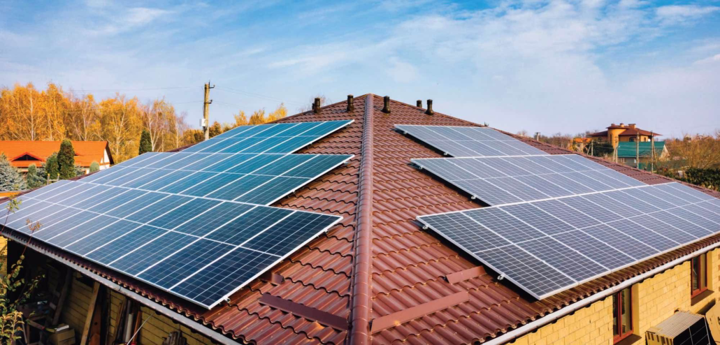
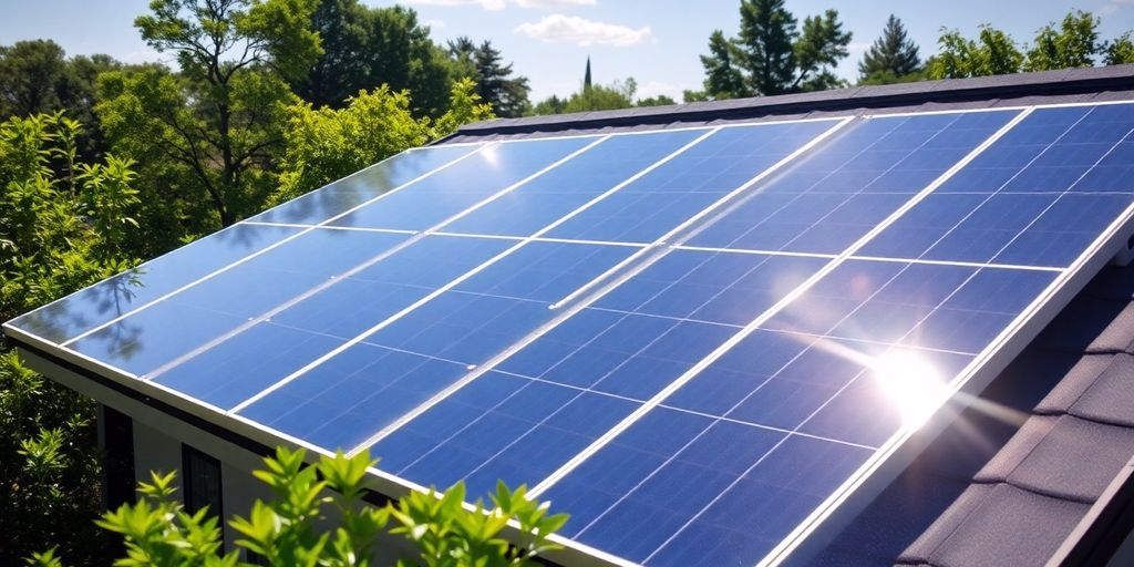
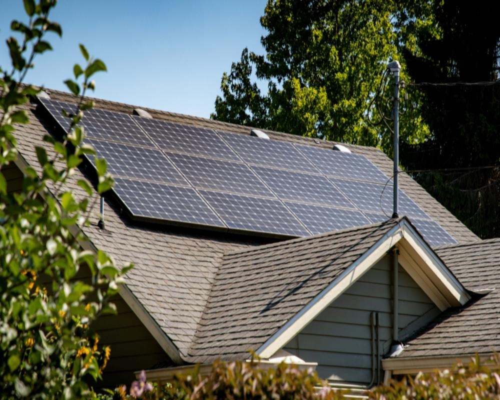
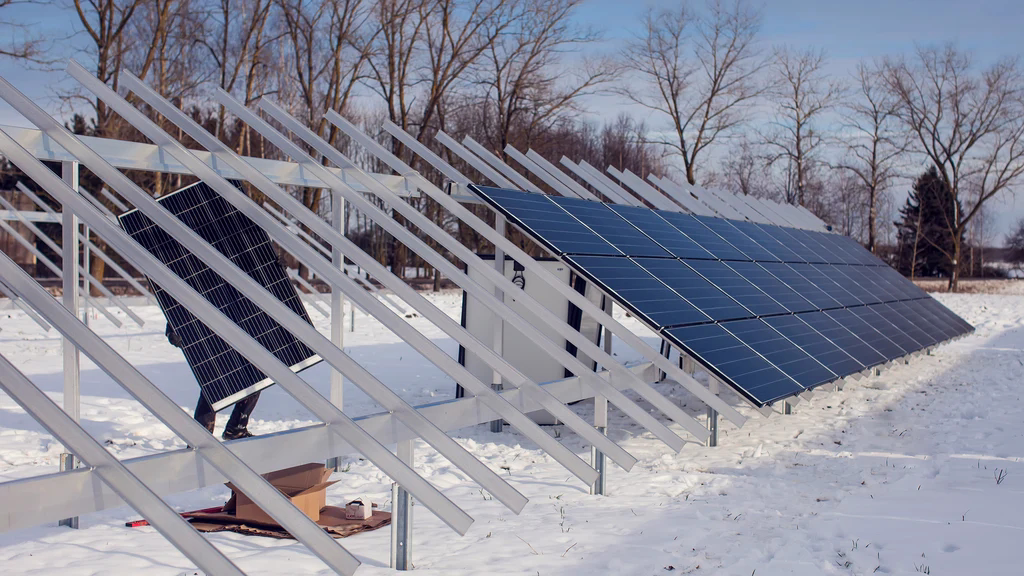
Next, consider the seasonal tilt effect. Adjusting the module tilt angle to a steeper angle for winter can significantly improve solar capture during shorter daylight hours. Design mounts that allow seasonal tilt-angle adjustments whenever possible, or choose ground-mounted arrays with a fixed tilt angle optimized for winter generation. For roof-mounted off grid solar home systems, consider adjustable mounts or microinverters to improve performance at low angles.

Off-Grid Solar Systems for Winter Solar Resources and Winter Irradiance (1)

Off Grid Solar Systems for Winter Use: Modular PV Array and Component Selection Strategies

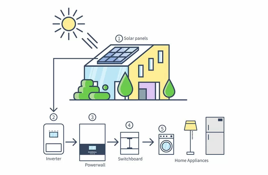
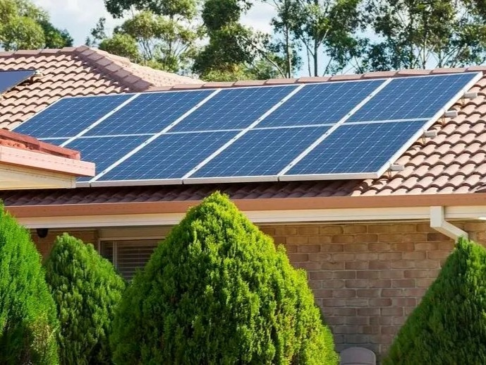
Selecting the right components and arranging a modular PV array is crucial for any off grid solar system for winter use. Therefore, we recommend choosing high-efficiency monocrystalline modules with excellent low-light performance and good temperature coefficients. In the long run, higher-efficiency modules increase power generation per unit area, which is especially important when roof or ground space is limited. The modular design of photovoltaic arrays allows engineers to use replaceable sub-arrays, or “strings,” so they can add or remove components without redesigning the entire system.

For example, the array can be built in modules of 2-4 components instead of one continuous large string. This provides flexibility in system operation—you can add components later to increase capacity, or isolate a string if it is damaged by snow or debris. Furthermore, modular design works seamlessly with module-level power electronics such as microinverters and DC optimizers. These devices reduce power losses caused by partial shading and enable each module to track its maximum power point independently.

Off-Grid Solar Systems for Winter Modular PV Array and Component Selection Strategies

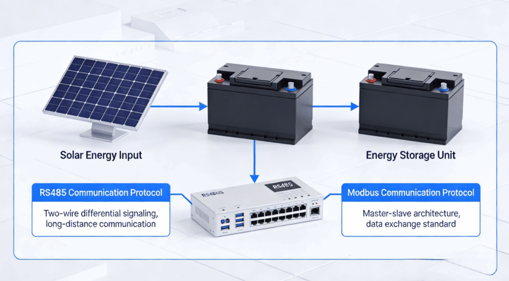
Battery Strategy: Chemistry, Insulation, and Modular Energy Storage

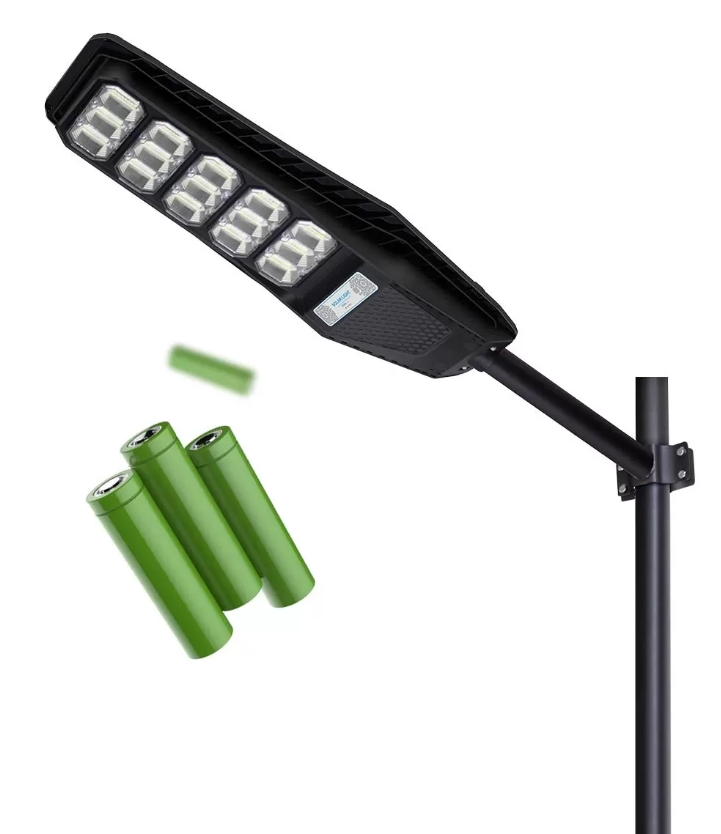
The performance of an off grid solar system in winter depends on its energy storage method. Batteries lose capacity and power in cold weather; therefore, you must choose an energy storage system that can maintain usable capacity and provide reliable power. The first step is choosing the right chemistry: Lithium iron phosphate (LiFePO4) batteries are becoming increasingly popular in off-grid home solar systems due to their long cycle life, high efficiency, and better cold-weather performance compared to some lead-acid batteries.

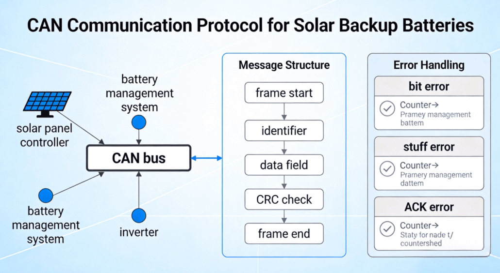
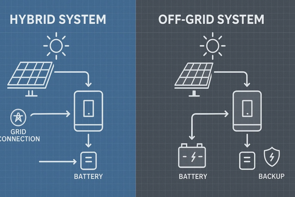
Modular battery packs offer several advantages. First, they allow for phased investment—starting with a smaller battery pack and expanding as needed. Second, modular systems provide redundancy: even if one module fails, the others can still maintain partial capacity. Third, modular design simplifies maintenance and replacement because technicians can service or upgrade individual modules without taking the entire system offline. For winter use, designers should combine modular batteries with insulated enclosures, thermostatically controlled heaters or heating elements, and an intelligent battery management system (BMS) that includes temperature sensors and charge/discharge control. Additionally, designers can consider a hybrid solution that combines battery storage with a backup generator or fuel cell to address prolonged periods of low sunlight.

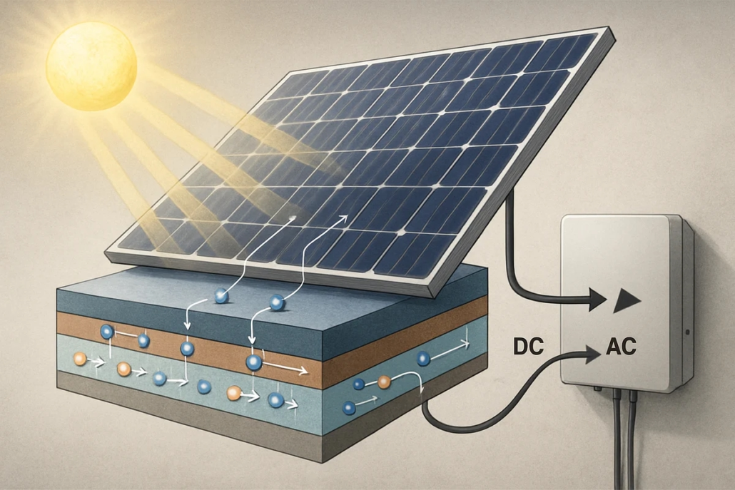
Inverters, Charge Controllers, and System Electronics

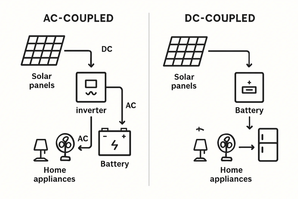
Power conversion and control electronics are core components of any off grid solar system for winter use. When choosing inverters and charge controllers, select models that are cold-weather resistant, can handle the maximum input power of the modular PV strings, and have sufficient capacity to meet peak load demands without frequent clipping. Use MPPT charge controllers; they offer superior efficiency in low light and varying light conditions, significantly improving energy utilization during winter months.

For modular off grid solar systems, choose inverter architectures that support parallel operation or have modular power stages. Power modules allow gradual capacity increases and provide redundancy: even if one inverter module fails, the others can continue powering critical loads. When integrating batteries, use inverter/chargers that can coordinate battery charging curves with the BMS; this prevents overcharging in cold temperatures and optimizes battery lifespan.

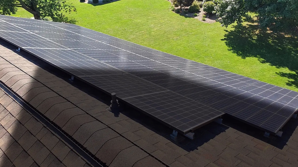
Best Practices for Winter Installation, Maintenance, and Snow Management

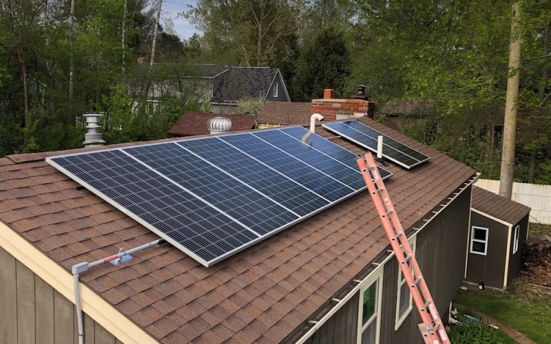
Installing an off grid solar system for winter use requires extra attention to initial construction and ongoing maintenance. First, site safety is paramount: control roof snow loads, ensure safe access for technicians, and adhere to building and electrical codes. Provide installers with winter-specific technical training, including installing snow guards, reinforcing mounting anchors, and using safe de-icing methods.

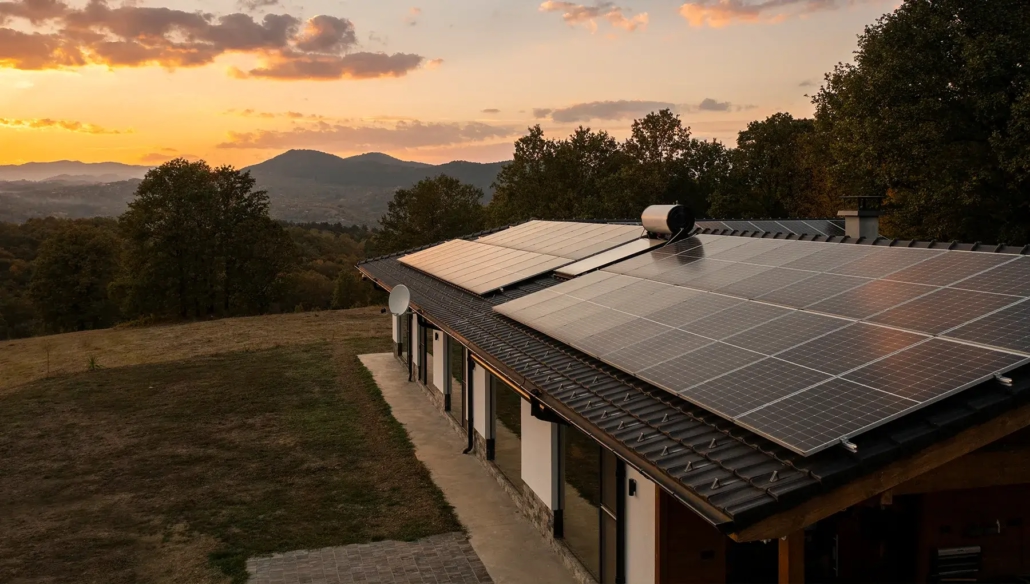
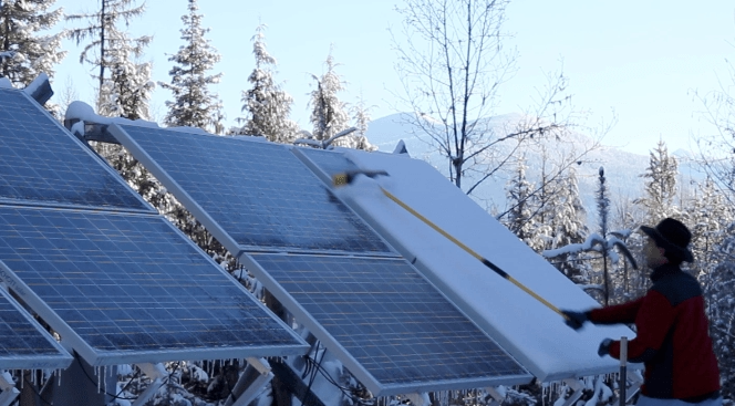
Heavy snow and dirt accumulation will reduce power generation; therefore, active and passive snow removal measures should be considered in the design. Passive snow-removal strategies include steeper tilt angles, smooth glass modules, and snow sheds. Active snow removal measures include manual snow removal, using heating cable systems in critical areas to melt snow, or even small robotic snowplows in commercial settings. However, active systems add complexity and energy consumption, so a cost-benefit analysis is necessary. For small off grid solar home systems, the most straightforward approach is to use a tilted, easily accessible mounting system and to perform regular manual cleaning after heavy snowfall. Maintenance includes regular inspections of wiring, connectors, and enclosures, especially after freeze-thaw cycles and storms, as these can damage seals.

Off-Grid Solar Systems for Winter Solar Resources and Winter Irradiance

Modular Design Ensures Long-Term Winter Power Capability

Designing an off grid solar system for winter use is not simply about adding more solar panels; it’s about building a resilient, modular energy architecture that can adapt to harsh seasonal conditions and growing demands. By combining a scalable off grid solar system layout with efficient PV modules, modular battery storage, intelligent inverters, and effective thermal and snow management strategies, users can maintain a stable power supply even on the shortest, coldest days of the year. The modular design of off-grid solar systems for winter use ensures long-term power during the winter months, maintaining a stable supply.

550W monocrystalline solar panel: High power density solves the problem of limited rooftop space

For homeowners, business owners, and municipalities looking to maximize rooftop solar energy capture, a 550W monocrystalline solar panel is a better option. Because these high-power-density solar modules deliver higher power within the same footprint as older, lower-power modules, they directly address the fundamental limitation of limited rooftop space. In fact, choosing 550W monocrystalline solar panels can maximize kilowatt-hour generation per square meter, simplify system design on constrained rooftops, and often reduce the balance-of-system costs per watt. High-efficiency monocrystalline solar panels typically utilize larger, more efficient cells and optimized cell interconnection methods to increase module output power without increasing area. Therefore, 550W monocrystalline solar panels outperform many 300-400W counterparts in terms of power per unit area.

Technical Advantages and Energy Yield of 550W Monocrystalline Solar Panel

550W monocrystalline solar panels offer numerous technical advantages that significantly improve the performance of rooftop solar systems. First, monocrystalline solar panels generally have higher conversion efficiency compared to traditional polycrystalline modules. This means higher DC power generation per square meter, which is especially important when rooftop space is limited. Second, many modern 550W modules incorporate cell-level technologies such as half-cut cells, multi-busbar designs, and improved wafer processing; these technologies collectively reduce resistive losses, improve shade tolerance, and enhance performance under partial shading conditions.

For systems with limited rooftop space, several technical parameters significantly impact annual energy yield: temperature coefficient, low-light sensitivity, and module degradation rate. Monocrystalline solar panels typically have better temperature coefficients than older designs, which is crucial for hot rooftop environments. Furthermore, modules optimized for low-light conditions can improve kilowatt-hour output in diffuse light environments.

In practice, choosing the right 550W monocrystalline solar panels can increase the annual energy yield from the same rooftop compared to lower-power options, thereby lowering the levelized cost of energy (LCOE) and shortening the payback period. Overall, the technical advantages of 550W monocrystalline solar panels help rooftop systems extract more usable energy within limited space while maintaining reliability and long-term performance.

Technical Advantages and Energy Yield of 550W Monocrystalline Solar Panels

Design and Installation Considerations on Limited Rooftops

Installing high-power 550W monocrystalline solar panel on limited rooftops requires careful design to maximize benefits and avoid potential problems. First, structural load assessment is crucial. While the weight per unit area of modern modules is roughly the same as that of many traditional panels, the final mounting structure layout will alter the point-load distribution and wind-load characteristics. Therefore, it is essential to engage a structural engineer or qualified installer.

Rooftop layout planning should prioritize module orientation, tilt angle, and shading analysis. Requiring fewer modules allows greater flexibility in array orientation and enables optimal irradiance capture; however, designers must avoid partial shading because it significantly reduces system performance. If partial shading is unavoidable, designers should use module-level power electronics to help ensure that each 550W monocrystalline solar panel operates near its maximum power output even when adjacent modules are shaded.

For mechanical installation on limited rooftops, custom mounting solutions may be more advantageous. Efficient cable management is also essential; fewer modules result in shorter wiring lengths to the combiner box and shorter rooftop conduit runs. When installing high-power modules in limited spaces, safety distances, maintenance access, and rooftop access requirements mandated by fire codes must not be overlooked.

Installation Solar Panels (1)

Electrical Compatibility, Inverters, and System Optimization for 550W Monocrystalline Solar Panel

Integrating 550W monocrystalline solar panels into a complete photovoltaic system requires electrical compatibility checks and adherence to best-practice optimization. Because these modules typically offer higher Voc and Imp than lower-power modules, string sizing and inverter selection must account for this difference. System designers should verify the inverter’s maximum input voltage, maximum string current, and maximum power point tracking (MPPT) voltage window to ensure safe and efficient operation.

For rooftop PV systems with limited space, maximizing the DC/AC ratio is a key strategy for increasing annual energy production. By using higher-power components, designers can achieve the desired AC output with fewer component strings, and a slight increase in the DC/AC ratio can often improve energy harvesting during off-peak hours.

For systems using 550W components, appropriate safety devices must be included, such as rapid-shutdown devices, arc-fault protection devices, and appropriately rated combiner boxes. Furthermore, for battery-based or hybrid power systems, pairing high-power-density solar panels with appropriately sized charge controllers and inverters maximizes energy capture within limited rooftop space for backup power or off-grid applications. Therefore, electrical compatibility and system-level optimization translate the inherent advantages of 550W monocrystalline silicon solar panels into reliable, efficient energy to meet the needs of constrained rooftop applications.

Durability, Warranty, and Long-Term Performance Considerations

Choosing a 550W monocrystalline solar panel requires considering not only short-term power density but also long-term reliability. Users should prioritize components from reputable solar panel manufacturers. Since rooftop-mounted solar panels are long-term assets, their degradation rate and ability to withstand environmental stresses are crucial.

High-quality monocrystalline silicon solar panels utilize tempered glass, robust frames, and improved encapsulation materials to reduce the risk of moisture ingress and delamination. Some 550W components employ advanced cell passivation and backsheet technologies to slow down cell performance degradation. It is essential to require third-party IEC testing to verify mechanical load (wind and snow), PID (Potential Induced Degradation), and thermal cycling performance. Furthermore, designers should consider the power temperature coefficient: a lower (less negative) temperature coefficient means better cell performance under the hot summer conditions common in many rooftop environments.

The durability of solar panels

Addressing Limited Rooftop Space with Higher Density

Typical applications for a 550W monocrystalline solar panel include: small residential rooftop systems, commercial buildings with limited but valuable rooftop space, carport installations with structural limitations, and retrofit projects where existing rooftop hardware or penetrations limit layout flexibility. For users with restricted roof space, these components offer higher power density, higher energy output per unit area, and potentially lower balance-of-system costs, enabling rooftop solar power generation in areas where traditional solar panels are not feasible.

How to Pick Solar street lights: Power Dream MJ-LH Model for Industrial Park Roads

For industrial parks, factory grounds, and community roads, reliable outdoor lighting is a crucial tool for ensuring safety, improving productivity, and protecting assets. Therefore, choosing the right solar street lights is not just about buying fixtures, but about selecting the appropriate energy source, control system, and form factor based on actual needs. PowerDream’s MJ-LH series solar street lights are designed specifically for industrial park roads and similar applications: they utilize high-efficiency polycrystalline silicon solar panels, lithium iron phosphate batteries, an intelligent control system including radar sensing, and offer multiple power options to meet varying lighting coverage needs and budgets.

Why do industrial park roads need dedicated solar street lights?

Industrial park roads and distribution yards have unique lighting requirements. These environments typically require broad, uniform illumination to ensure safety; reliable operation under various weather conditions; and low-maintenance solutions to reduce operating costs for large numbers of streetlights and long-distance lighting. Ordinary solar lights designed for residential sidewalks cannot reliably meet these needs.

Key industrial requirements:

  • Higher lumen output and better optical control to illuminate wide lanes, loading docks, and intersections.
  • Robust batteries with deep discharge capabilities to maintain autonomous operation for several days, even with insufficient sunlight.
  • Intelligent control for energy savings and safety in areas with intermittent human presence.
  • Durability and low maintenance to ensure reliable operation even when unattended for extended periods.

The MJ-LH series solar street light is designed specifically for these applications. Each MJ-LH fixture uses a high-efficiency 4V/18W polycrystalline silicon solar panel as the primary energy collector, designed to quickly collect solar energy in both sunny and cloudy conditions and charge the built-in LiFePO₄ battery. The lithium iron phosphate battery offers safe, stable deep-cycle performance and a long lifespan – crucial for installations the require replacing dozens or even hundreds of streetlight batteries.

Furthermore, MJ-LH series models feature intelligent control functions, including remote control, radar sensors, and three configurable lighting modes, enabling operators to balance brightness, runtime, and energy consumption precisely. Therefore, this solar streetlight series meets the performance and reliability requirements of industrial park roads.

Why do industrial park roads need dedicated solar street lights

How do solar panels and lithium iron phosphate batteries extend nighttime operation?

Energy harvesting and storage determine the actual performance of a solar street light. Two parameters are most critical: the energy the solar panel collects daily and the usable energy the battery can store and reliably release for many years.

Solar Panel Specifications:

High-efficiency polycrystalline silicon solar panel (4V/18W). Power Dream selected this size panel to achieve fast charging at the typical installation tilt angles and orientations common in industrial parks. The 18W rated power ensures continuous daytime charging even under partial shading, allowing the system to replenish battery power quickly in sunny or cloudy weather. In addition, for durability, the MJ-LH solar street light panel uses a tempered glass laminate, is coated with an anti-reflective coating, and features a robust junction box to resist moisture and mechanical stress, which is crucial for roadside deployment.

Battery Specifications (Lithium Iron Phosphate Battery):

Lithium iron phosphate (LiFePO₄) offers advantages such as long cycle life (typically over 2000 cycles at 80% depth of discharge), good thermal stability, and safe chemical properties, making it suitable for outdoor lighting. These characteristics make LiFePO₄ a wise choice for MJ-LH solar streetlights, which require years of reliability and safe deep-discharge performance.

The importance of this combination lies in achieving longer nighttime operation. The rapid energy harvesting from the solar panel, combined with the deep-cycle capacity of the lithium iron phosphate battery, extends nighttime operation. In fact, depending on the model and lighting mode, the MJ-LH device can maintain lighting for multiple nights with insufficient sunlight. The low degradation of the lithium iron phosphate battery ensures stable performance for many years, reducing maintenance and replacement cycles and lowering the total cost of ownership.

How do solar panels and lithium iron phosphate batteries extend nighttime operatio

Intelligent Control and Safety Features of Solar Street Lights

Today, the functionality of solar street lights goes beyond just lighting; they must also intelligently manage energy and respond to usage and operational constraints. The MJ-LH solar street light provides a flexible control system that helps balance lighting needs and energy budgets. Smart Control Features:

Remote Control: Operators can control the lights remotely, reducing the need for on-site configuration and enabling centralized management for industrial park deployments.

Intelligent Lighting Control: The MJ-LH platform supports time-based dimming, dusk-to-dawn mode, and adaptive strategies to extend battery life while meeting safety standards. For example, the default setting maintains 30% to 50% of the rated output at night and increases to 100% at a preset time or when motion is detected.

Radar Sensor: Advanced radar sensing technology detects moving objects over a broader range than simple PIR sensors. Radar sensors provide stable detection performance in various weather and temperatures, allowing MJ-LH luminaires to dynamically increase brightness when vehicles or pedestrians pass by and dim the brightness when the area is unoccupied.

How to Choose Between Sizes and Models?

PowerDream’s MJ-LH series offers three model levels to meet a range of lighting needs, from narrow lanes to wide industrial corridors.

MJ-LH9300 (300W): Best suited for areas with narrow coverage, side roads, sidewalks, or locations with limited budgets.

MJ-LH9400 (400W): Provides balanced brightness and coverage for standard industrial park roads. This model is suitable for main internal roads, medium-width lanes, and areas with moderate nighttime vehicle activity. Depending on the required uniformity, pole spacing is expected to be in the range of 20-35 meters.

MJ-LH9500 (500W): A high-output lighting solution for large coverage areas, main roads, or locations requiring high brightness and long battery life. The MJ-LH9500 is particularly suitable for wide lanes, roundabouts, and areas requiring consistently high visibility. It supports larger pole spacing and longer battery life for extended illumination.

When choosing, please clearly specify your lighting requirements. Illuminance levels and uniformity targets can be determined based on road class and safety standards. Industrial park designs typically set road illuminance targets at 10-20 lux, with higher targets for critical loading and unloading areas. Also, consider pole spacing and mounting height: taller poles increase coverage but may reduce illuminance; consider glare and pole budget when choosing mounting options. Simultaneously determine energy and autonomy goals. If the site requires multiple nights of autonomous operation, choose the MJ-LH9500 with a larger battery pack or reduce the rated power to conserve energy.

How to Choose Between Sizes and Models?

Providing suitable road lighting solutions

PowerDream’s MJ-LH solar street lights combine high-efficiency polycrystalline silicon solar energy harvesting, long-life lithium iron phosphate battery energy storage, and an intelligent control system to meet the demanding lighting needs of industrial park roads, sidewalks, and roadside areas. When selecting MJ-LH luminaires, you can choose the appropriate model based on coverage targets, plan the installation scheme using professional photometric data, and ensure efficient and safe operation with remote management capabilities.

Will a solar on grid system Work During Power Outages? Backup Solution Guide

How can you ensure your home still has power during a power outage when using a solar on grid system? This is one of the most frequently asked questions by grid-tied solar users. Therefore, this guide will explain whether a standard solar on grid system can provide power during a power outage and introduce reliable backup power solutions to ensure you have electricity even when the grid fails. You will learn about anti-islanding safety regulations, inverter and battery technologies for backup power, the differences between AC-coupled and DC-coupled configurations, and design strategies (whole-house backup power vs. critical-circuit backup power).

Can a solar on grid system provide power during a power outage?

Standard on grid solar systems are designed to work in conjunction with the utility grid. Their inverters convert the DC electricity generated by the solar panels into AC electricity, synchronizing the frequency and voltage with the grid. This synchronization is crucial for safe and efficient grid connection. Still, it also introduces a safety rule: when the grid goes down, the inverter must stop supplying power to the grid. This behavior is called anti-islanding.

Why is anti-islanding necessary?

Because it’s necessary to protect line maintenance personnel, if the inverter continues to supply power to a de-energized line, technicians working on the line could be injured by back-fed current. Utility workers need to ensure that de-energized lines are completely de-energized. Additionally, it protects equipment. An islanded system operating without control could produce unsafe voltages and frequencies, potentially damaging household appliances and the inverter itself.

How does the inverter force a shutdown?

On grid inverters continuously monitor the grid’s voltage and frequency. When they detect a grid outage, such as a step change in frequency or the disappearance of the voltage waveform, they stop producing AC power within a few cycles. Therefore, a typical on grid solar system without batteries or other special equipment cannot provide any useful power to the home during a power outage.

Can a solar on grid system provide power during a power outage

Anti-Islanding, Regulatory Requirements, and the Need for Inverters with Islanding Capability

If you want your solar on grid system to power loads during a power outage, your system must intentionally create and control an electrical island independent of the grid. This capability involves regulations, standards, and inverter functionality.

Key Standards and Regulations:

UL 1741 / IEEE 1547 (USA): These standards specify the safety and grid interconnection requirements for inverters. Modern testing requires “smart inverters” to exhibit specific behaviors. IEEE 1547 specifies how distributed power sources interact with the grid.

Utility Interconnection Agreements: Utilities require clear documentation of system behavior, how the system disconnects during power outages, how it limits power output when the grid is present, and how it resynchronizes after grid restoration.

Local Electrical Codes: National and local electrical codes specify transfer equipment, circuit breakers, and wiring requirements for backup circuits.

What is an Inverter with Islanding Capability?

Hybrid Inverters: These can form a grid in a standalone state. They include control functions for setting island voltage and frequency, accepting solar and battery inputs, managing charging and discharging, and interfacing with transfer switches. Depending on their functionality, they are sometimes referred to as on grid or off-grid inverters.

Transfer Switches and Safety Devices:

To safely provide backup power, the system must disconnect from the grid using an automatic transfer switch (ATS) or manual transfer switch, which isolates the home’s circuits from the grid before powering them. The ATS monitors the grid status and seamlessly switches the load to the battery/inverter when the grid fails. Simply put, to ensure your on grid solar system provides reliable backup power, you must use code-compliant equipment and configurations that intentionally isolate and prevent dangerous backfeeding.

Anti-Islanding, Regulatory Requirements, and the Need for Inverters with Islanding Capability

Batteries and Hybrid Inverters: How They Provide Backup Power During Power Outages

Adding energy storage can transform a on grid solar system into a more resilient power source. Batteries store excess solar energy when the grid is operational and power the home when the grid is down. The core components include batteries, a battery-compatible hybrid inverter or separate inverter/charger, and transfer/control logic.

How do Batteries Enable Backup Power?

Energy Buffering: When there is ample sunlight but the grid is down, the battery can immediately power loads that would otherwise be without power. During the day, PV generation powers the loads and charges the battery, and at night, the battery provides the stored energy. Seamless Switching: A hybrid inverter with an automatic transfer switch (ATS) automatically switches the house to island mode in the event of a grid failure. At this point, the inverter manages the battery output and any available photovoltaic input.

Load Management: Due to limited battery capacity, the system typically implements load prioritization (critical load panel) or automatic load shedding to extend backup time.

Hybrid Inverter Architecture:

Integrated hybrid inverters combine an MPPT solar inverter and a battery inverter/charger in a single enclosure, simplifying installation and control. Many commercially available inverter models for residential systems fall into this category.

An inverter + separate battery inverter/charger combination allows for the use of dedicated components, such as a high-performance PV inverter with a dedicated battery inverter/charger. This offers greater flexibility for retrofit projects.

When a battery is added to a on grid solar system with a suitable inverter, it can be transformed into a backup power system. The quality of the user experience largely depends on the inverter’s performance and system design.

The Impact of AC-Coupled vs. DC-Coupled Battery Systems on Backup Power Performance

When integrating batteries into an on grid solar system, you will encounter two primary coupling methods: AC coupling and DC coupling. Each method impacts performance, efficiency, and upgrade flexibility.

AC-Coupled Systems:

Architecture: The solar array is connected to the grid via an inverter; the battery is connected to the AC side via a battery inverter/charger or a hybrid inverter. The energy generated by the PV system is converted to AC power, which can then be used, sent to the battery inverter to be converted to DC power to charge the battery, or exported to the grid.

Advantages: Ideal for retrofitting existing systems; you can add batteries and a battery inverter to an existing on grid solar system. Compatible with a wide range of inverters and has lower initial investment costs.

Considerations: The slightly more conversion steps when charging the battery from the PV system may reduce round-trip efficiency. However, modern hybrid inverters minimize losses, and flexibility is often more important than efficiency losses.

DC-Coupled Systems:

Architecture: The PV DC power is connected to a charge controller or a DC-coupled inverter, directly supplying the battery DC bus, and then a single inverter converts the DC power to AC power for the load. Advantages: Direct photovoltaic charging can be more efficient. Tight integration can reduce losses in specific operating modes and provide better battery charging control.

Considerations: Retrofitting may be more complex; system design is crucial for maximizing benefits. DC coupling is often the preferred solution when optimizing PV charging efficiency in off-grid or tightly integrated systems.

Hybrid Approach:

Some modern systems use a combination of AC and DC coupling to optimize retrofit flexibility and charging efficiency. For example, a hybrid inverter can accept both PV DC input and AC-coupled battery inverter input, and coordinate energy flow.

So, which is best for backup? For on grid solar system owners who want to add backup power to an existing array, AC-coupled solutions are generally more straightforward and quicker to deploy. For new projects where maximizing round-trip efficiency is a priority, DC-coupled systems may be attractive. Both methods can provide reliable backup when properly designed.

The Impact of AC-Coupled vs. DC-Coupled Battery Systems on Backup Power Performance

Backup Power Design for Solar on grid system

When you decide to add backup power to an on grid solar system, you must choose a strategy: power the entire house or only critical circuits. Each choice impacts cost, complexity, and user experience.

Essential Load Method:

Approach: Install a transfer switch that connects a portion of the circuits to the inverter/battery during a power outage. A separate sub-panel powers these critical loads.

Advantages: Lower battery capacity and inverter power requirements, resulting in lower overall cost. Faster deployment is commonly used in residential installations.

Limitations: Non-critical circuits remain off during a power outage.

Whole-House Backup:

Concept: The inverter/battery system provides sufficient capacity and power to run all or most household circuits. Larger battery banks and higher-powered inverters are needed to handle heavy loads (e.g., HVAC, electric water heaters, EV chargers).

Advantages: Complete resilience – the house functions normally during many power outages.

Limitations: Significantly increased cost and space requirements. Inverter and battery capacity must meet peak load and surge requirements (for motors and compressors). Cost and Return on Investment Considerations

Backup batteries significantly increase project costs, requiring planning for equipment, installation, permitting, and potential electrical service upgrades. Evaluate the benefits: the value of power outage protection, optimized energy bills, reduced demand charges, and possible incentives.

For many homeowners, a critical load power supply solution offers a balance of reliability and cost. For those seeking complete energy independence, a whole-house power system is the best option, though it comes at a significantly higher price.

Recommended Methods for Achieving Reliable Backup Power

solar on grid systems cannot power your home during a power outage because the on grid inverter automatically shuts down for safety reasons. This protects utility workers and equipment, but leaves homeowners vulnerable during outages. The good news is that adding a properly designed battery storage system and appropriate inverter/conversion hardware can transform your on grid system into a reliable asset that provides backup power.

Therefore, we recommend adding a battery inverter or hybrid inverter and an automatic transfer switch (ATS) to your existing on grid solar system to create critical load backup power. This method is cost-effective and quick. For new systems, an integrated hybrid inverter and appropriately sized battery should be used to maximize efficiency and performance. When designing on grid solar systems with backup capabilities, we prioritize safety, clarity, and practicality.

Supported communication protocols for solar backup batteries: CAN/RS485/RS232 compatible

Solar panels, inverters, battery banks, and home energy management systems (HEMS) not only need to function correctly but also work in tandem. Communication acts as an invisible bond, connecting these devices into a reliable and resilient energy system. Reliable communication is crucial for solar backup batteries: it relates to safety, performance optimization, warranty support, and grid interaction. In this guide, I’ll walk you through three of the most common wired protocols—CAN, RS485, and RS232—and explain how they can be applied to solar backup batteries for home.

Communication Protocol Requirements for Solar Backup Batteries

When evaluating solar backup batteries, communication requirements can be categorized as follows:

  • Real-time monitoring and telemetry: State of charge (SoC), voltage, current, temperature, state of health (SoH), and fault codes.
  • Control commands: Charge/discharge setpoints, reserve capacity limits, grid connection mode switching, and emergency disconnection.
  • Configuration and services: Firmware updates, parameter tuning, logging, and diagnostics.
  • Energy Management Integration: Exchanges data with inverters, smart meters, or battery storage systems to enable demand response, peak shaving, and time-of-use pricing strategies.
  • Safety and Protection Coordination: Quickly exchanges alarm information (overcurrent, overtemperature) and remote shutdown.

Three main wired communication standards are used in battery applications:

CAN: A robust, low-latency multi-node bus widely used in battery management systems (BMS), microgrid controllers, and automotive applications. It excels at handling deterministic messages for safety-critical controls.

RS485: A multi-point differential serial link commonly used in inverter-storage integration and industrial telemetry. It is ideal for connecting multiple devices over medium distances and is common in SunSpec and many commercial energy systems.

RS23: A traditional point-to-point serial interface primarily used for local configuration, service consoles, and short-range device-to-PC connections.

They each play different roles: CAN typically handles internal BMS and high-speed safety messages; RS485/Modbus connects the battery to the inverter, EMS, and meter; RS232 provides service-level access. Powerdream’s solar backup battery typically supports all three interfaces to maximize interoperability with a wide range of inverters, gateways, and monitoring tools.

Communication Protocol Requirements for Solar Backup Batteries

CAN Communication Protocol for Solar Backup Batteries

What is the CAN bus, and why is it suitable for batteries?

The CAN bus is a fieldbus developed initially for automotive networks. It uses differential signaling and an open arbitration/priority mechanism, so messages from high-priority nodes can deterministically gain bus access. For residential solar backup batteries, the CAN bus offers several advantages:

  • Low latency and real-time behavior: Very useful for safety-critical switching.
  • Strong differential signaling: Good noise immunity over the cabling commonly found in battery boxes or cabinets.
  • Multi-node architecture: Allows multiple BMS modules, inverters, and battery controllers to share a single bus.

Common CAN Implementations in Solar Backup Battery Systems

CANopen: An application layer protocol containing an object dictionary, device profiles, and standard service types. CANopen BMS profiles standardize SoC/SoH message and parameter access.

J1939: Originally used in heavy vehicles, J1939 is also used in mobile and industrial applications and supports priority data transmission.

Proprietary CAN: Many battery vendors use custom CAN frames to implement advanced functions, meaning integration may require vendor-provided mappings or gateway conversions.

In practical applications, the CAN bus in solar backup batteries can connect the internal BMS network to the battery monitoring module, thermal sensors, and the central BMS. It enables control from the battery to the inverter/protected device and supports clustered battery arrays, where multiple battery cells function as a single energy source, requiring rapid synchronization.

CAN Communication Protocol for Solar Backup Batteries

RS485 and Modbus Communication Protocols

Why are RS485/Modbus so popular? Because RS485 is a physical-layer standard, it provides balanced differential signaling over a two-wire bus. When used in conjunction with Modbus RTU (a simple master-slave protocol), RS485 becomes the standard language for industrial energy equipment. Inverters, meters, and gateways also widely support RS485/Modbus for solar backup battery applications.

In battery systems, they are primarily used for battery inverter integration, enabling the inverter to query the battery’s state of charge (SoC) and available capacity, and issue charge/discharge commands. They also facilitate EMS and SCADA connections, allowing the energy management system to poll the battery for telemetry data and coordinate system-wide policies. Furthermore, they enable multi-device networking; RS485 supports multi-point networks, allowing multiple devices to be connected to the same pair of wires.

RS232: Traditional Integration for Service Consoles and Installers

RS232 is an earlier, simpler point-to-point serial communication protocol. While not suitable for multi-node networks, its role in a solar backup battery is:

Local configuration and debugging: Connecting a laptop to the battery controller for firmware updates, log retrieval, or parameter configuration.

Diagnostics and Repair: RS232 is still typically used as a service port for software packages that do not require continuous telemetry.

Legacy Support: Some older inverters and controllers still use RS232 for single-point telemetry.

In practice, we recommend using RS232 only for commissioning and troubleshooting; for production telemetry, RS485 or CAN is preferable. Use a USB-to-RS232 adapter known to be compatible with battery drivers and terminal software. When using RS232 in noisy environments, optical isolation or a temporary USB adapter should be used for service sessions.

RS232 Traditional Integration for Service Consoles and Installers

Which Protocol Should Be Chosen? When Should a Gateway Be Used?

Interoperability is a frequently asked question by customers: “My inverter supports Modbus, but the battery supports CAN. What should I do?” The answer is to match each protocol to its functionality and apply a gateway where needed.

Typical Architecture Options:

Native Modbus/RS485 Battery + Modbus Inverter: Best practice – The inverter polls the battery directly. Use SunSpec whenever possible to simplify register mapping.

CAN Native Battery + CAN Native Inverter: This is the preferred solution when both devices support the standardized CAN protocol (CANopen or a vendor-defined protocol). It provides low-latency, stable control.

Hybrid Environment (CAN Battery + Modbus Inverter): Utilizes a protocol gateway or converter. The gateway converts CAN messages into Modbus registers or higher-level templates. PowerDream solar backup batteries typically include optional gateway modules or firmware layers to provide necessary telemetry data via Modbus.

Cloud/IoT Assist: Some systems use a local gateway to convert RS485/CAN signals to MQTT/HTTPS signals for cloud monitoring; a cloud service then coordinates the setpoint. This facilitates remote updates but increases reliance on internet connectivity and requires security considerations.

Choosing a Reliable Communication Method for Secure and Flexible Solar Backup Batteries

Communication is central to a secure and efficient solar backup battery. The CAN bus provides a low-latency, deterministic link, ideal for battery management systems (BMS) and fast, secure signal transmission. RS485 (supporting Modbus and SunSpec) is the primary interface for interoperability between inverters and energy management systems (EMS). RS232 remains a vital service port for commissioning and diagnostics. A reliable solar backup battery solution typically supports all three interfaces, providing flexibility during installation and enabling long-term integration with a wide range of inverters and energy management systems.

Upgrading to Monocrystalline Solar Panels Boosting a Home’s Output by 18%

When you power your home with solar panels, your roof acts like a miniature power plant. Now, if you replace the core component of that power plant—the silicon wafers that convert sunlight into electricity—with more efficient technology, that same roof can generate significantly more energy for weeks and years to come. Upgrading to monocrystalline silicon solar panels is precisely this kind of transformation, allowing you to capture more solar energy and convert it into usable kilowatt-hours of electricity. In many real-world retrofit cases at Power Dream, homeowners have seen an overall increase in system power generation of approximately 18% after upgrading. We’ll also show you that monocrystalline silicon cells have superior electrical characteristics. When you redesign your system around them, you can achieve real energy gains without increasing your roof area.

Monocrystalline Solar Panels: The Technological Advantage of More Energy Per Square Foot

The Monocrystalline solar panel are made from single-crystal silicon. This uniform crystal lattice structure reduces electrical losses and improves the open-circuit voltage and fill factor of the cells—two variables that directly impact module efficiency. Compared to typical older polycrystalline or early multicrystalline modules, monocrystalline silicon solar panels offer several technological advantages that combine to deliver higher annual energy yields:

Higher Nominal Efficiency: Modern monocrystalline modules typically have nominal efficiencies between 19% and 23%. This means that a monocrystalline array can generate more DC power for the same roof area.

Better Low-Light Performance: The superior electrical characteristics of monocrystalline cells allow the modules to extract more energy during periods of low light intensity, such as cloudy mornings, evenings, and winter months, which significantly impacts daily energy production.

Lower Degradation Rate: High-quality monocrystalline silicon solar panel manufacturers typically guarantee an annual degradation rate of 0.3%-0.6%, which is better than older technologies. Over ten years, a lower degradation rate means higher efficiency and thus increased cumulative energy savings.

Advances in Cell Structure: PERC, half-cut cells, bifacial designs, and TOPCon/tandem methods are almost always first applied to monocrystalline silicon wafers and perform best on them. When you replace existing solar panels on your roof with more efficient monocrystalline silicon solar panels, the energy generated per square foot of exposed panel area increases. Since most residential roofs have limitations on the number of panels that can be installed, increasing panel efficiency is the most direct way to improve the system’s annual energy production without expanding the roof area.

Upgrading to Monocrystalline Solar Panels Boosting a Home’s Output by 18%

How to calculate and verify an 18% system output increase?

For solar system upgrades, switching to a monocrystalline silicon solar panel can increase power generation by approximately 18%, a conservative estimate supported by data and verifiable through field testing. The following steps detail how to quantify this increase, adjust it based on real-world conditions, and verify its applicability to residential solar retrofits, all metrics that align with performance in typical sunny regions of the United States.

Step 1: Establish a Polycrystalline Baseline System

Calculate starting with a standard older solar system using mid-range polycrystalline silicon solar panels, which serves as the industry benchmark for comparison:

Core specifications: Panel efficiency 17%, rated power 5.0 kW (DC)

Actual annual energy production: 6,800 kWh/year

6,800 kilowatt-hours per year is the baseline for measuring the output gain after the monocrystalline upgrade.

Step 2: Calculate Core Monocrystalline Output Increase

Upgrading to an equally sized monocrystalline solar panel (with a mainstream efficiency of 20%, a reasonable figure for industry standards) directly increases power generation because solar power generation is directly proportional to the efficiency of the panels per unit area. The core calculation uses a simple efficiency ratio formula: New energy ≈ Old energy × (New efficiency / Old efficiency)

Applying baseline specifications and monocrystalline specifications:

6,800 kWh/year × (20% / 17%) = 6,800 × 1.176 ≈ 8,000 kWh/year

This is equivalent to an increase of 1200 kilowatt-hours per year, a 17.6% increase in annual production—approximately 18% in practical terms for industrial and residential applications.

Step 3: Adjust the 18% Increase Based on Real-World Conditions

The core 17.6% performance increase calculation is based on identical system components and conditions. In reality, monocrystalline silicon upgrades can deliver additional performance improvements, often exceeding the 18% increase. The following conservative, real-world added value applies to most US retrofit projects:

1. Monocrystalline cell performance advantages: Temperature resistance and low-light efficiency can provide an additional 1-3% yield in many US climates, reducing energy losses under high temperature or cloudy conditions.

2. Eliminating aging polycrystalline silicon problems: Replacing old panels addresses microcracks, panel misalignment, and degraded anti-reflective coatings—restoring the yield lost by older systems due to wear and tear.

3. Monocrystalline design features: Half-cut cells and upgraded internal wiring reduce resistive losses and improve shading tolerance, adding a small but consistent number of kilowatt-hours to annual energy production.

4. BOS component upgrades: Optimizing the balance of system (BOS) components (e.g., new inverters) and panel layout during the retrofit further enhances performance.

Taken together, these factors ensure that the fundamental 17-18% efficiency improvement can easily meet or exceed the 18% increase in output for most residential solar upgrade projects.

How to calculate and verify an 18% system output increase

Monocrystalline Silicon Solar Panel Design and Component Selection

Upgrading components is necessary, but not sufficient. To fully realize the approximately 18% performance increase, you must redesign or reconfigure the system so that the solar panels, inverters, wiring, and control systems work together.

1. Appropriately Sized Inverters and MPPT Architecture

If you are replacing with higher-power modules, re-evaluate the inverter’s power rating. A moderate increase in the DC/AC power ratio (e.g., 1.1-1.3:1) can increase power generation in the mornings and evenings while avoiding excessive clipping at midday. Use modern inverters with high CEC/European efficiency and low no-load losses.

2. Re-examine Wiring and Connections.

Higher-power modules produce higher currents; ensure your wires, fuses, and combiner box equipment are appropriately sized. Resistive losses in DC wiring reduce gains; shortening wire lengths and increasing wire size can compensate for lost power. Also, when replacing with higher-power modules, re-evaluate anti-islanding and rapid-shutdown requirements to comply with local regulations.

3. Installation and Tilt Angle Optimization

If upgrading under existing conditions, maintain the tilt and azimuth angles – but pay attention to row spacing for bifacial or taller modules. If reducing the number of modules or changing the layout, ensure a shading check is performed on the winter solstice to avoid new row shading that would offset the gains.

4. BOS Upgrade: Inverters, Optimizers, and Monitoring

Upgrading to modern inverters with higher partial load efficiency can increase actual energy capture. Simultaneously, robust monitoring capabilities can be added to detect performance deviations and allow for quick action. Small daily losses accumulate over time, and monitoring maximizes long-term returns.

Monocrystalline Silicon Solar Panel Design and Component Selection

Why is an 18% increase in yield so economically significant?

It only makes sense if the increased energy output improves household finances.

Case Example: Impact of Upgrade on Annual Production and Revenue

Using the benchmark data mentioned earlier: an old system generates 6,800 kWh per year. After the upgrade, generation increases to approximately 8,000 kWh per year (an 18% increase), a net gain of 1,200 kWh/year. If your electricity price is $0.18 per kWh, the additional energy is equivalent to: $216/year.

This is pure added value on top of the cost savings already achieved by the original system. However, the economic benefits will be even greater if the following factors are considered:

1. Avoiding Inverter Replacement and BOS System Upgrades

Module upgrades are often performed concurrently with inverter or BOS system upgrades. Installing modern, high-efficiency inverters reduces parasitic losses and further increases power generation beyond the module efficiency improvement.

2. Incentives and Tax Credits

If you commission the upgrade during the period when federal investment tax credits (ITC) or local government subsidy policies are in effect, the net cost will be reduced, thus improving the return on investment. Some regions offer equipment-level subsidies for high-efficiency monocrystalline silicon modules or performance-based incentives based on electricity generation.

3. Increased Net Metering or Export Value

In regions with favorable export credit policies, higher output can lead to more export revenue closer to the retail price. Even with net metering limitations, using a greater share of the total production for self-consumption can reduce expensive purchases during peak hours, especially when combined with a small battery system.

4. Reduced Risk and Long-Term Energy Savings

Because monocrystalline solar panels typically experience less performance degradation and perform better over time, they reduce the risk of declining energy savings. This lower risk profile makes the investment more attractive and helps protect household budgets from rising utility costs.

18% Increase in Household Electricity Generation

Upgrading to monocrystalline solar panels typically increases household electricity generation by approximately 18%, as monocrystalline panels convert sunlight more efficiently, perform better in low-light and high-temperature conditions, and degrade more slowly. However, this figure is not a guarantee; it is based on a system-level upgrade that includes components, inverters, wiring, installation, and maintenance. For homeowners with limited roof space who want to increase solar power generation without expanding their building footprint, upgrading to monocrystalline silicon solar panels is an efficient, technically feasible option. With proper preparation and professional system commissioning, you can expect a significant increase in annual electricity generation.

Solar Micro Inverter vs String Inverter: Efficiency & Shade Tolerance Comparison

As solar energy systems evolve from simple rooftop installations to highly optimized power generation assets, the choice of inverter technology has become a critical factor in determining system performance. Many users focus on solar panel power or battery capacity, but actual efficiency often depends on how effectively solar energy is converted, managed, and protected under non-ideal conditions. This is where the choice between solar micro inverter and traditional string inverters becomes essential. At PowerDream, we share this information with you not from a marketing perspective, but from an engineering and performance-driven standpoint. This article provides a clear, data-driven comparison of solar micro inverters and string inverters by examining efficiency metrics, shading tolerance, and energy harvesting accuracy.

Efficiency Metrics of Solar Micro Inverter and Their Impact on Energy Output

When evaluating any photovoltaic system, efficiency is not a single number but a combination of metrics that collectively determine how much solar energy is converted into usable AC power, whether for the solar micro inverter or string inverters.

The following three metrics are most important:

Peak (DC-to-AC) Conversion Efficiency: This is the maximum percentage of DC power from the solar panels that the inverter can convert to AC under ideal test conditions. PowerDream micro inverters achieve a peak efficiency of up to 93%.

CEC Weighted Efficiency: This more realistic metric weights the inverter’s performance across a range of operating voltages and temperatures, providing a more accurate representation of real-world performance. PowerDream microinverters boast a CEC efficiency of up to 92%, demonstrating strong conversion capabilities at actual operating points.

Tracking Efficiency: This refers to the inverter’s ability to keep the photovoltaic modules operating at their Maximum Power Point (MPP) under varying light intensities and temperatures. PowerDream microinverters achieve a tracking efficiency of up to 99%, meaning the inverter’s MPPT algorithm can capture virtually all available DC power from each module at all times.

Why are these differences so significant? Consider the following: String inverters may have slightly higher peak efficiency, but this figure assumes that all modules in the string are operating under identical conditions. On a real rooftop, modules have varying azimuths, tilt angles, and shading conditions. When there are differences in the output power of the components, the central maximum power point tracking (MPPT) function of string inverters must compromise, and the operating point of the entire string will shift towards the component with the lowest performance. Solar microinverters, on the other hand, perform MPPT on each element, so each component can independently contribute its maximum power. Therefore, their tracking efficiency (99%) can usually compensate for the slightly lower peak conversion efficiency, as the system captures more total DC energy before conversion.

Efficiency Metrics of Solar Microinverters and Their Impact on Energy Output

Detailed Explanation of Shading Tolerance and Component-Level Optimization of Solar Micro Inverter

Shading is a fatal weakness for many solar systems. Even brief shading of a single cell string within a module can significantly reduce the power output of the entire module; in string inverter systems, underperforming modules drag down the performance of the whole string. This is where the advantage of the solar micro inverter architecture lies.

How does shading affect string inverter systems?

In a typical string inverter system, solar panels are connected in series to achieve the target DC voltage. The string inverter performs MPPT on the entire series circuit. When one panel is shaded, its current output drops; because a series circuit requires uniform current, the current of the whole string drops to the level of the shaded component. Therefore, string inverter systems have poor shading tolerance: a shaded area covering 10% of the array area can, in some cases, lead to more than 10% energy loss, depending on how the shading affects the cells and modules. Furthermore, mismatches between modules exacerbate this problem.

How do solar micro inverters handle shading?

Solar micro inverters are connected to each component and perform MPPT locally. When one component is shaded, the solar micro inverter optimizes only that component. The other components continue to operate near their maximum power point. In effect, this makes the system more tolerant to shading, series mismatches, and soiling.

Key shading-related advantages of component-level micro inverters:

Linear recovery: As the shading moves, the component output recovers independently; the rest of the array remains unaffected. Granular Monitoring: Micro inverters provide performance data for each component, simplifying shading diagnostics and maintenance.

Better Performance Under Partial Shading: On real-world rooftops with obstructions, microinverters typically generate more annual energy than comparable string inverter systems.

Quantifiable Benefits

The improvement in shading tolerance depends on the shading pattern, orientation diversity, and sunlight hours, but typical field tests show that arrays equipped with micro inverters perform several percentage points better than string systems on partially shaded residential rooftops, and the advantage is even greater on complex roofs. For example, a partially shaded string of solar panels might lose 30% to 50% of its expected power generation at a given moment. In contrast, a microinverter system only loses the power generation of the shaded components. This difference in environments prone to shading can translate into actual increases in annual energy yield and shorter payback periods.

How do solar micro inverters handle shading (2)

Comparison of Actual Energy Output and Performance Under Different Conditions

When choosing between solar micro inverters and string inverters, you should consider not only instantaneous efficiency data but also the system’s annual energy yield. Let’s analyze the main factors that determine actual output and compare the performance of each type of inverter under these variables.

Scenario A: No Shading, Uniform Roof, Commercial Scale

On large ground-mounted or flat rooftops with uniform orientation and minimal shading, string inverters typically perform well. Their higher peak efficiency (usually 97%–98%), lower per-watt hardware cost, and centralized maintenance model can lead to slightly higher return on investment when components are identical and sunlight is abundant. In this scenario, the component-level Maximum Power Point Tracking (MPPT) advantage of microinverters is less significant. However, they still offer some advantages: component-level monitoring, ease of scalability, and reduced risk of DC wiring issues.

Scenario B: Residential Rooftop, Partial Shading and Varying Orientations

In this scenario, micro inverters typically outperform string inverters in annual energy yield—for example, a 6 kW system with solar panels installed on both north- and south-facing rooftops. String inverters require separate string configurations for each roof face to avoid power mismatch. Microinverters, on the other hand, can seamlessly handle power from both north and south-facing arrays and extract near-MPP power from each module. In these configurations, PowerDream microinverters offer tracking efficiency up to 99% and high conversion efficiency (CEC 92%).

Scenario C: Soiling, Degradation, and Aging

Over time, module mismatch increases due to dust accumulation, microcracks, and varying degrees of module aging. The solar micro inverter localize the effects of this aging. A faulty or soiled module only affects its own microinverter output, while a string inverter would cause a power reduction across the entire system. Therefore, unless all modules age at precisely the same rate, a microinverter array will maintain higher energy production over the long term.

Example of Actual Yield

For example, consider a suburban residential roof with minimal shading and two orientations. A simulated string inverter system might generate 8,000 kWh annually; a solar microinverter system might generate 8,600 kWh annually (approximately a 7.5% increase) because each module tracks its own MPP, and shading losses are limited to the affected modules.

Residential Rooftop, Partial Shading and Varying Orientations

Reliability, Monitoring, Safety, and Lifecycle Maintenance

When evaluating solar inverter architectures, reliability and maintenance considerations, along with conversion efficiency, impact the total cost of ownership. Microinverters and string inverters have different failure modes, service models, and safety features.

Reliability and Mean Time Between Failures:

String inverters, with their centralized design, are generally robust; they are larger and handle higher DC currents. If a string inverter fails, the entire array goes offline until it is repaired. Solar microinverters distribute the conversion task across multiple smaller units; a single microinverter failure only affects one module, while the rest continue to operate normally. PowerDream microinverters are designed for outdoor, module-level applications with high protection ratings and thermal performance. When installed correctly, modern microinverters have a long lifespan and support remote firmware updates.

Monitoring and Diagnostic Capabilities:

Solar microinverters excel in granular monitoring. Each component reports power, voltage, and sometimes temperature, providing installers and users with a continuous performance picture. This data facilitates quick diagnosis of shading issues, component replacement, and performance optimization. String inverters also offer monitoring capabilities, but only at the string level; without additional component-level power electronics (optimizers), they cannot isolate underperforming individual components.

Safety and Electrical Risks:

From a safety perspective, solar microinverters reduce the need for high-voltage DC wiring in rooftop installations. Because the module performs AC conversion internally, the rooftop circuit operates at a lower, safer voltage, and the AC wiring provides greater safety for firefighters and technicians. String inverters require long runs of high-voltage DC wiring on the roof or in the attic. While string inverters and system designs mitigate risks through rapid-shutdown and current-limiting features, microinverters inherently minimize the dangers associated with DC electricity.

Making the Right Choice

If your installation project involves significant shading, complex roof orientations, or you require precise monitoring and safety assurances for each component, solar microinverters are generally the better choice. For large-scale, uniformly distributed arrays designed to minimize the levelized cost of electricity (LCOE), string inverters may still be a suitable option. Ultimately, the choice should be based on the specific conditions of your site and your maintenance capabilities.

What is the Ideal tilt angle for a rooftop solar panel?

Consider two identical houses. Both have the same monocrystalline solar panel model and the same solar panel kit installed, but one house has its roof panels installed flat, while the other uses the optimal tilt angle. After a year, the tilted system generates significantly more clean energy, resulting in lower electricity bills and a faster return on investment. Therefore, subtle changes—adjusting a few degrees, slightly altering the direction—can accumulate into significant differences in performance, cost-effectiveness, and carbon reduction. As a supplier, PowerDream can help customers make these small but crucial design choices. So we’ll tell you how to determine the optimal tilt angle for your rooftop solar panel.

How does the tilt angle affect rooftop solar panel output?

To choose the ideal tilt angle, you first need to understand that the sun’s apparent movement across the sky varies with latitude, season, and time of day. The tilt angle determines the angle at which sunlight strikes the panel surface. The more perpendicular the sunlight, the more energy the panel converts; conversely, a smaller angle results in greater reflection losses and lower instantaneous power output.

Key concepts to understand:

Angle of Incidence: The angle between the incoming sunlight and the panel surface. The smaller the angle of incidence (the more perpendicular the sunlight hits the panel), the more power is generated.

Latitude Rule of Thumb: For fixed (non-adjustable) rooftop solar panels, a common starting point is to set the tilt angle approximately equal to the latitude of the location. This approach maximizes annual energy production in many places.

Seasonal Adjustment Rule of Thumb: To increase winter energy production, the tilt angle can be increased by approximately 15 °; to increase summer energy production, it can be decreased by approximately 15°. These adjustments help match seasonal load patterns.

Panel Orientation (Azimuth): Both tilt angle and azimuth are essential. In the US, rooftop solar panels facing due south (azimuth ≈ 180°) with a tilt angle equal to the local latitude typically achieve the highest annual energy production. East or west-facing arrays can also perform well, but may require adjusting the tilt angle and slightly increasing capacity to achieve the same annual energy production.

How does the tilt angle affect the output of rooftop solar panels

Tilt Angle Recommendations for Rooftop Solar Panel Based on Climate and Latitude

Different climates and load profiles require distinct tilt-angle strategies. Here are some practical starting points and examples:

1. Temperate Mid-Latitude Regions (approximately 30°–45° North or South latitude)

Recommended fixed tilt angle: Approximately equal to the latitude.

Reason: Balances summer and winter power generation, making it suitable for year-round residential electricity needs.

Seasonal adjustment: If your household uses more electricity in winter (heating, lighting), increase by 10°–15°. If you use more electricity in summer (air conditioning, pool pump), decrease by 10°–15°.

2. Low-Latitude/Tropical Regions (approximately 0°–25°)

Recommended fixed tilt angle: Latitude or slightly less than the latitude (latitude minus 5° to latitude).

Reason: The sun is higher in the sky throughout the year; near-horizontal or low tilt angles capture diffuse sky radiation and provide stable summer power generation.

Seasonal adjustment: Usually not necessary; minor adjustments can be made if considering the rainy season.

3. High-Latitude/Subpolar Regions (>45°)

Recommended fixed tilt angle: Latitude or latitude plus 10° to optimize winter power generation.

Reason: The sun angle is lower in winter, so a larger tilt angle helps capture low-angle sunlight and promotes snow shedding.

Seasonal adjustment: For systems designed to generate more winter energy or for roofs with significant snow accumulation, consider increasing by 20°.

4. Snowy Climates

Tilt angle priority: A larger angle (> the latitude) helps snow slide off and prevents long-term dust accumulation. Steeper roof solar panel tilt angles reduce snow cover time and allow for faster recovery of power generation after snowstorms.

5. Sunny, Dry Climates

Tilt angle priority: Optimize at the latitude location for maximum annual power generation. Be aware of dust accumulation – the tilt angle affects cleaning frequency and power losses from dust. Remember: These are just initial suggestions. Always conduct a site-specific solar resource assessment and horizon/shading analysis when finalizing the tilt angle for your solar panel system design.

Tilt Angle Recommendations for Rooftop Solar Panel Based on Climate and Latitude

Why do roof and mounting systems limit the angle of rooftop solar panels?

Pitched Roofs

In most cases, the roof pitch equals the tilt angle of the panel array: the panels are mounted flush with the roof surface, so the tilt angle of the panels is the same as the roof pitch. If your roof pitch is close to the recommended angle (latitude), you will get optimal performance at the lowest cost. Otherwise, consider using small-angle mounting brackets to slightly adjust the tilt angle, while accounting for structural and drainage implications.

The advantages include low installation costs, an aesthetic appearance, and lower wind loads when mounted flush. The disadvantage is that if the roof pitch deviates significantly from the optimal angle, you will lose some annual power generation.

Flat Roofs

Adjustable brackets are standard: you can set the panels to an angle and orientation close to the optimal tilt angle. For rooftop solar panels on flat roofs, the angle of the tilt brackets is typically between 10° and 30°, depending on structural factors, wind load, and aesthetic requirements.

Exceptional Cases: Dormer Windows, Mansard Roofs, and Obstacles

Micro-tilt or multi-array layouts can help. Instead of forcing all arrays to have the same tilt angle, the system can be divided into multiple sub-arrays, each facing a different roof plane. The solar panel kit may include various small inverters or micro-inverters to ensure that each sub-array operates near its maximum power point.

In practice, many residential rooftop solar panel installations use the roof pitch as the actual working tilt angle. The performance loss due to a few degrees of deviation from the latitude is usually slight, especially for monocrystalline solar panel modules, which have relatively high temperature stability and performance at different angles of incidence.

Why do roof and mounting systems limit the angle of rooftop solar panels


Seasonal Tilt, Tracking, and Technology Choices

If you want to improve performance from your rooftop solar panels, consider seasonal adjustments, single-axis trackers, or panels that respond differently to tilt and shading (e.g., monocrystalline silicon).

Seasonal Tilt Adjustment:

Manually adjustable racks allow you to adjust the tilt angle twice a year (summer and winter). This is a low-cost compromise solution to improve seasonal output: a tilt angle of -15° in summer and +15° in winter.

Cost-effectiveness:

For many residential systems, the annual gains from seasonal adjustments are not significant, but if your household’s seasonal load fluctuates considerably, the extra gains can be valuable.

Tracking Systems:

Single-axis trackers allow solar panels to rotate throughout the day, increasing annual energy production by 10% to 25% compared to fixed-tilt installations in many climates. Due to structural, wind, and roof-penetration limitations, tracking technology is less common in rooftop solar systems. Ground-mounted solar panel kits more frequently utilize tracking technology. Dual-axis trackers maximize instantaneous output but are rarely practical on rooftops due to their complexity and cost.

Monocrystalline Silicon Solar Panels and Tilt Sensitivity

Monocrystalline silicon Panels have higher module efficiency and tend to perform better under high irradiance and partial shading conditions. Their higher efficiency makes them ideal for situations where roof space is limited, and the tilt angle cannot be optimized.

Bifacial modules can utilize reflected light (albedo) for additional power generation and typically require a higher mounting height (to utilize ground reflection). The tilt angle affects the power output of bifacial modules; generally, a moderate tilt angle combined with appropriate ground treatment can improve the power generation from the back side.

Final Tilt Angle Recommendation

For most residential users, set the tilt angle of your rooftop solar panels to approximately your latitude and focus on high-quality monocrystalline silicon modules and a robust solar panel kit. If winter energy consumption (heating, lighting) is a priority, increase the latitude by approximately 15°. If summer energy consumption (air conditioning) is a priority, decrease the latitude by approximately 15°. In many cases, it’s better to accept a moderate loss in output rather than making complex structural changes; panel area and orientation are often more important than minor tilt differences.

While the tilt angle is essential, it is only one of many factors that determine the actual performance. As a supplier of rooftop solar panels, PowerDream recommends that you first determine your latitude and then optimize the tilt angle based on your home’s electricity load, roof limitations, and a simple financial model.

Are hybrid solar power systems more efficient than off-grid systems?

Two neighboring farms have both installed solar panels and batteries. Still, one connects its system to the local grid using a hybrid solar power system, while the other operates completely off-grid. During variable weather and peak evening demand, one system seamlessly draws power from the grid when needed and sells excess solar power back to the grid during midday; the other carefully conserves battery power and sometimes activates a backup generator. Which approach is more energy efficient? The answer depends on how you define efficiency. We will analyze the evidence and trade-offs from a professional engineering perspective to help you decide whether hybrid solar power systems or a completely off-grid solution better meets your efficiency, resilience, and environmental goals.

Hybrid Solar Power Systems vs. Off-Grid Systems

A hybrid solar power system integrates photovoltaic power generation, energy storage, and grid connection. It allows for bidirectional power flow: solar to load, solar to battery, solar to grid (export), and grid to battery or load when needed. In contrast, an off-grid solar system operates independently, balancing generation, storage, and consumption needs without drawing power from the public grid. Off-grid systems typically include a backup diesel generator to ensure reliable operation during extended periods of insufficient sunlight.

Key architectural differences determine how we compare efficiency:

  • Energy Sources and Flexibility: Hybrid solar power systems can utilize the grid as an additional energy “source” or “sink.” Off-grid systems are limited to on-site generation and storage.
  • Operating Strategy: Hybrid solar systems can optimize charging and discharging behavior based on time-of-use pricing, grid carbon intensity, or export incentives. Off-grid systems are optimized solely for local generation and storage management.
  • Loss Pathways: Hybrid systems introduce increased component and control complexity (inverters, grid relays), but benefit from the grid’s balancing capabilities. Off-grid systems avoid some losses (no grid export circuitry), but may experience increased generator run time and reduced battery cycling efficiency.

Efficiency is multidimensional: we can discuss technical, economic, and environmental efficiency. In many cases, hybrid solar systems can improve overall efficiency by reducing energy waste and optimizing scheduling across more options. However, the specific results depend on the system design, local grid carbon emission structure, electricity pricing mechanisms, climate patterns, and load profiles.

Hybrid Solar Power Systems vs. Off-Grid Systems

Key Metrics for Measuring the Efficiency of Hybrid Solar Power Systems

Before determining which method is “more efficient,” it’s important to define the metrics used to measure it. We typically use the following core metrics:

  • System Round-Trip Efficiency (RTE): For comparisons centered on energy storage, RTE measures the energy returned to the load divided by the energy input to the battery. A higher RTE means less energy is lost during the energy storage cycle.
  • Self-Consumption Rate (SCR): The proportion of on-site solar power generated that is consumed locally rather than exported to the grid. Off-grid systems typically aim for a self-consumption rate close to 100%; hybrid solar systems can adjust the self-consumption rate based on the economic benefits of grid export.
  • Self-Sufficiency Rate (SSR): The proportion of total load supplied by on-site generation over a period of time. Off-grid systems aim for SSR = 100%; hybrid systems aim for a high SSR, but can draw power from the grid when necessary.
  • Net Carbon Emission Reduction: This refers to the cumulative carbon dioxide emissions avoided by using on-site solar and energy storage systems compared to baseline grid consumption and generator use.

Hybrid solar power systems typically improve real-time energy efficiency (RTE) in practice by reducing unnecessary battery cycling and generator starts. For example, if the grid provides low-carbon or low-cost electricity during certain periods, a hybrid energy management system (EMS) can use this energy rather than curtail PV generation or inefficiently cycle batteries. Conversely, purely off-grid systems may force batteries to extreme depths of discharge (DoD) or require frequent generator starts, reducing cycle efficiency and increasing effective losses per kilowatt-hour (kWh).

Energy Conversion and Storage Efficiency Compared to Off Grid Systems

From a technical perspective, efficiency losses occur in the conversion (PV → DC → AC), in storage (battery charging and discharging), and in any auxiliary power generation. Let’s look at how hybrid solar systems differ from off grid solar systems. Inverter and Conversion Losses: Both systems use inverters and charge controllers; modern hybrid inverters integrate multiple power-electronics modules to handle current from PV, batteries, and the grid. Under optimal load, inverter conversion efficiency can reach 95% to 98%. Hybrid solar power systems may introduce additional conversion steps during grid charging and discharging, but advanced designs minimize these extra losses through efficient topologies.

Battery Round-Trip Efficiency (RTE): Typical lithium-ion batteries currently have an RTE of 85%–95%. Off grid systems that rely heavily on battery cycling experience numerous cycles and are therefore highly sensitive to RTE and depth of discharge. Hybrid solar power systems can reduce the number of deep cycles by using grid power during prolonged periods of low solar irradiance or by exporting excess solar energy when the battery is fully charged, thereby reducing overall battery throughput and extending battery life.

For many practical applications, the greater flexibility of hybrid systems translates to higher system-level efficiency: it minimizes fuel consumption, reduces unnecessary deep battery cycling, and maximizes the utilization of PV assets across multiple loads.

Energy Conversion and Storage Efficiency Compared to Off Grid Systems (1)

Operational Flexibility and Practical Performance Comparison

The operating strategy determines whether a hybrid solar power system actually delivers higher efficiency in practice.

Hybrid solar systems equipped with modern EMS can optimize charging and discharging based on forecasts, electricity prices, and carbon intensity. Consider the following three scenarios:

  • Solar-Priority Mode: The system first uses available PV generation to meet load demand and charge the battery, drawing power from the grid only when the energy storage system is depleted. This maximizes the use of local renewable energy and reduces electricity imports.
  • Economic Mode: The EMS charges the battery from the grid during off-peak electricity prices and discharges it during peak prices, thus reducing electricity costs but not necessarily minimizing carbon emissions.
  • Carbon-Aware Mode: The EMS primarily charges the battery using solar energy or low-carbon grid periods (e.g., nighttime nuclear or low-carbon power supply) and discharges during high-carbon grid periods to minimize emissions.

Off-grid systems lack these grid-interactive capabilities. They must prioritize reliability, maintain sufficient energy storage to sustain autonomous operation, and use generators as backup power when needed. Off-grid systems maximize independence but may sacrifice efficiency when generator usage increases during the rainy season. Hybrid solar power systems, on the other hand, strive to strike a balance: maintaining autonomous operation during short power outages and drawing on grid power during prolonged periods of low sunlight. In many commercial applications, hybrid generators can reduce operating time by 60% to 90% compared to off-grid generators with equivalent autonomous operation capabilities. This reduction can significantly save fuel and improve operational efficiency.

Choose the right system based on your energy efficiency goals and site conditions.

The choice between a hybrid or off grid system depends on clear objectives:

If the grid is reliable, a hybrid solar power system is generally superior to an off-grid system in terms of efficiency and economics. Off-grid systems are more suitable where there is no grid or the grid is unreliable, and energy independence is essential. Furthermore, if you require weeks of autonomous operation, the off-grid system must be large enough, even if efficiency is slightly lower. For most residential and commercial users, a hybrid system with a moderately sized battery capacity provides sufficient reliability and higher efficiency.

Additionally, for homes with flexible loads, hybrid solar systems can shift energy consumption to low-carbon periods, thereby achieving higher actual energy efficiency. Fixed, always-on critical loads, however, require larger energy storage capacity and may even necessitate off-grid power.

Consider multiple dimensions to make the best choice for you.

Are hybrid solar power systems more efficient than off-grid systems? In most real-world applications with a reliable grid, the answer is yes—hybrid systems are generally more efficient overall. They reduce generator usage, avoid the need for unnecessarily oversized battery banks, and enable smarter scheduling, extending equipment lifespan and minimizing lifecycle carbon emissions. However, if absolute independence is necessary, an off-grid system is the only option.

A complete guide to compliance for lithium ion solar batteries

When you install a row of aesthetically pleasing battery racks behind your solar panels, expecting them to operate quietly for years, you might encounter shipping delays, failed inspections, or even worse, avoidable safety incidents. Compliance isn’t just a buzzword; it’s fundamental to the reliable performance, legal market access, and long-term reputation risk management of lithium ion solar batteries. Both manufacturers and users need to understand which rules apply, why they exist, and how to comply with them to ensure a reliable solar battery solution.

Global Compliance Landscape for Lithium Ion Solar Batteries

Regulations and standards for lithium ion solar batteries cover multiple areas: cell and battery pack safety, system-level fire performance, electrical codes for installation, transportation regulations, and environmental/sustainability obligations. Each regulation serves a purpose. Cell and battery pack standards set basic safety requirements for electrical, thermal, and mechanical abuse. System-level standards address thermal runaway propagation and fire behavior in assembled battery energy storage systems. Installation codes dictate safe electrical connections and disconnections at the building level. Transportation regulations ensure the safe transport of lithium batteries by road, rail, sea, and air.

A compliant lithium ion solar battery should incorporate compliant international and regional standards, specifically IEC 62133 for portable cell/battery safety and IEC 62619 for industrial and stationary applications; these standards define tests for electrical abuse, short circuits, mechanical shock, and thermal behavior, thus forming the foundation of a compliant lithium ion solar battery. Certification to these standards demonstrates that your lithium-ion solar battery meets recognized safety performance benchmarks. At the system level, UL 9540A widely serves as a test method for evaluating the thermal runaway fire characteristics of battery energy storage systems—a critical consideration when installing in buildings or enclosed spaces.

IEC 62133

Cell and Battery Pack Safety Standards

At the heart of every compliant lithium ion solar battery are tested and certified cells and battery packs. Standards such as IEC 62133 (portable batteries) and IEC 62619 (industrial/stationary batteries) define minimum safety performance for batteries through a series of tests, including electrical cycling, overcharging, forced discharge, thermal stability, short-circuiting, vibration, shock, and mechanical crushing. These standardized tests simulate reasonably foreseeable misuse and abuse scenarios, ensuring that the cells and battery packs can operate safely under these conditions without catastrophic failure.

Why is this so important in practical applications? If a lithium ion solar battery cell or battery pack fails during these tests, thermal runaway can occur. To ensure safety standards, PowerDream’s lithium batteries feature cells with complete test records and a compliant Battery Management System (BMS) that provides cell-level protection: overvoltage, undervoltage, overcurrent, and temperature limits. We also provide documentation and test evidence at the battery pack level, demonstrating that the assembled battery pack meets the IEC 62619 or IEC 62133 standards required for the target application.

Cell and Battery Pack Safety Standards

System-Level Safety and Fire Testing

Even if individual battery packs meet cell and pack standards, system-level risks can still arise in multi-pack configurations. Thermal runaway can propagate between modules. Therefore, system-level testing and risk mitigation measures are crucial for large-scale stationary lithium ion solar batteries.

The UL 9540A battery test method characterizes the thermal runaway fire behavior of a complete battery pack or typical components. It tests how a single-cell or module failure propagates, releases gases, and the challenges it poses to fire suppression or control measures. Building code officials often require UL 9540A test evidence or system design justification for indoor energy storage systems or systems installed in enclosed spaces. Furthermore, NFPA 855 and updated electrical codes also impose requirements on the installation and fire safety of energy storage systems, including spacing, ventilation, fire suppression, and emergency disconnect devices. In short, system-level testing addresses the question of “what happens in large-scale applications,” and regulators require data and mitigation strategies before approving the installation of lithium ion solar batteries.

Cell and Battery Pack Safety Standards

Electrical Codes, Installation Rules, and Site Compliance for Lithium Ion Solar Batteries

Electrical installation codes ensure that your lithium solar batteries are safely integrated into building and grid systems. National and local electrical codes specify requirements for wiring, grounding, circuit breakers, emergency shutdowns, and labeling. In the United States, the National Electrical Code (NEC) has added and refined sections on energy storage; for example, Article 706 covers energy storage systems and includes provisions for circuit breakers, enclosures, and system-specific labeling. Similarly, many jurisdictions supplement the NEC with local amendments or by adopting relevant standards (such as NFPA 855) to address fire and safety concerns.

To ensure compliance at the installation site, follow this practical checklist:

  • Ensure the system design meets local code requirements for overcurrent protection, circuit breakers, and wire ratings.
  • Provide written documentation for emergency isolation and emergency responder procedures—clearly marking disconnect locations and providing hazard signage.
  • Implement monitoring interfaces and remote shutdown capabilities as required by code or the authority having jurisdiction. Many jurisdictions require readily accessible emergency shutdown devices to disconnect the system from power.
  • Collaborate with licensed electricians and code consultants during the design and commissioning process. Early coordination with the authority having jurisdiction helps avoid unexpected requirements and expedites the approval process for lithium-ion solar battery installations.

Shipping, Packaging, and International Transport Compliance

The transportation of lithium solar batteries—whether cells, battery packs, or replacement modules—is subject to strict transportation regulations. Section 38.3 of the UN Manual of Tests and Criteria (UN38.3) specifies test items such as altitude simulation, thermal cycling, vibration, shock, external short circuit, impact, overcharge, and forced discharge. Passing UN38.3 testing is typically a prerequisite for air, sea, and road/rail transport. Carriers and freight forwarders will require test documentation before accepting shipments, and non-compliant shipments may be delayed or refused.

Best practices for transportation compliance include:

  • Ensure that each cell or battery type shipped has a UN38.3 test report and certification. Keep test records readily available for customs and carrier inspection.
  • Use approved packaging to prevent short circuits and physical damage. For large modules or racks, frames and transportation restraints typically secure them.
  • Properly classify the goods and apply the required hazard labels and documentation according to the International Air Transport Association Dangerous Goods Regulations (IATA DGR) and the International Maritime Dangerous Goods Code (IMDG). Note that airlines and shipping companies are often conservative—some even prohibit lithium battery shipments entirely.

The Importance of Battery Compliance

Compliance is crucial for lithium ion solar batteries, which must adhere to applicable standards and regulations: IEC 62133 / IEC 62619 for battery/battery pack safety; UL 9540A and UL 1973 for system-level and battery energy storage system (BESS) regulations; UN38.3 for transportation; and regional environmental regulations such as the EU Battery Regulation for fulfilling lifecycle obligations. A structured compliance documentation package should be built, including third-party test reports, supplier traceability, firmware control logs, and clear installation documentation. As a professional lithium-ion battery manufacturer, we ensure that the lithium batteries we provide feature robust battery management systems (BMS) and undergo certified testing.