How can 20kW off grid solar systems transform the energy independence of rural farms?

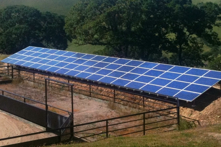
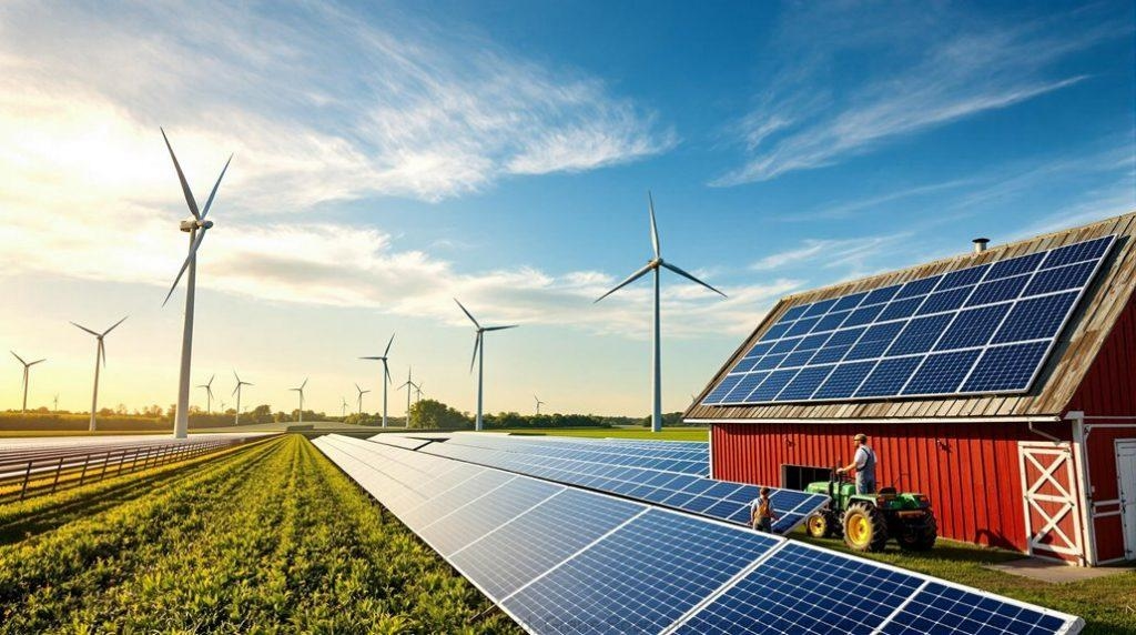
For many small and medium-sized rural farms and other remote areas, choosing off grid solar systems can significantly enhance energy independence. A 20kW off-grid solar system is an ideal choice, as it can simultaneously meet the needs of multiple critical loads such as water pumps, milking machines, refrigeration equipment, lighting, and household electricity, while also being more cost-effective than larger commercial solar arrays. Agricultural production typically combines a continuous base load with intermittent high-power electricity demands. The 20kW peak power generation capacity helps manage daytime peak loads, especially when the solar panels are oriented to maximize power output at midday. At the same time, battery storage compensates for insufficient power on cloudy days and at night.

Off-Grid Solar Systems Design Structure Suitable for Rural Farms

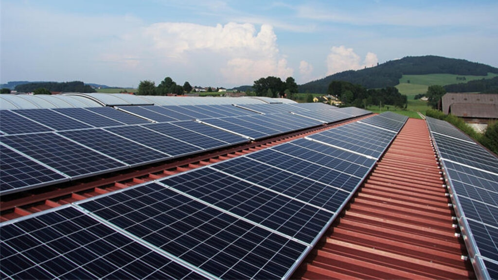
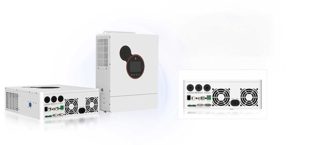
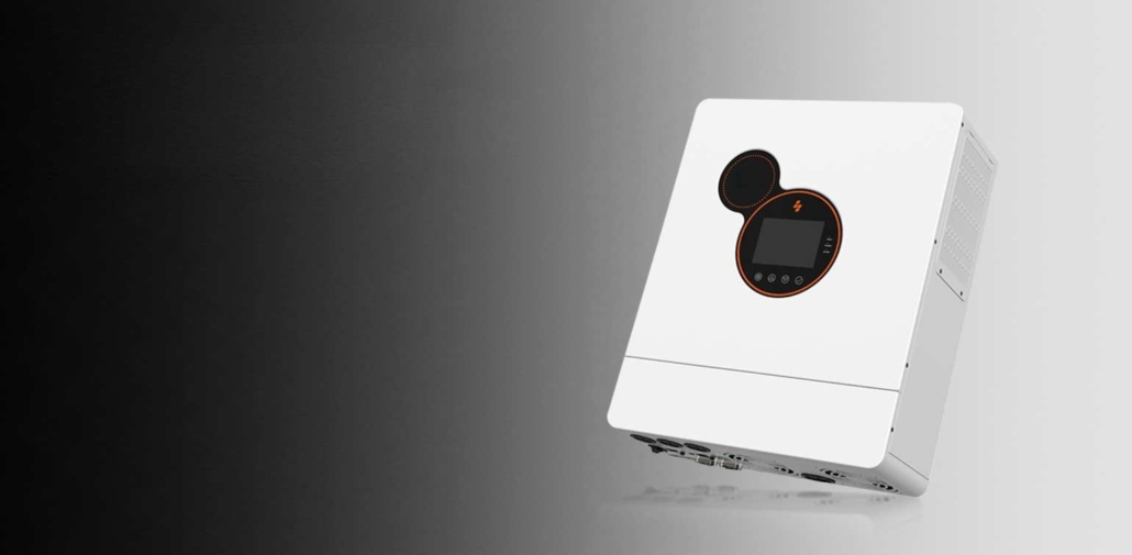
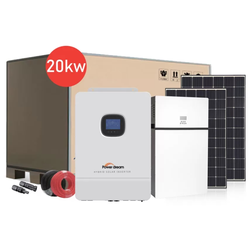
A reliable off grid solar system integrates power generation, conversion, storage, and control. PowerDream’s 20kW off grid solar power system is a prime example of a well-designed system: it consists of 36 x 550W monocrystalline silicon solar panels, 4 x 5kW pure-sine-wave off-grid inverters, and 2 x 51.2V lithium batteries equipped with a smart battery management system.

The 36 x 550-watt monocrystalline silicon solar panels offer high power efficiency and excellent performance in low light conditions. This configuration optimizes rooftop or ground-mounted layouts and concentrates power generation in a compact space, particularly important for farms with limited area. The four 5kW off-grid inverters provide pure sine-wave output, delivering precise, clean power suitable for sophisticated agricultural electronic equipment, variable-speed water pumps, and refrigeration compressors used on rural farms. Pure sine wave output minimizes harmonic distortion, protects motors, and maintains instrument accuracy.

The two 51.2V lithium battery packs provide energy buffering to meet the farm’s nighttime electricity needs and power requirements during consecutive cloudy days. Compared to lead-acid battery systems, lithium batteries offer higher cycle efficiency, longer lifespan, and superior depth-of-discharge characteristics. They can also be monitored in real-time via a mobile application, allowing farm operators to track power generation, consumption, and battery status. These components together form a powerful off-grid solar system that supports continuous farm operations with minimal human intervention.
off grid solar systems 1-1

Matching Off Grid Solar Systems: Generation, Storage, and Farm Load

Performance planning is key to achieving energy independence. A 20kW off grid solar power system must consider not only instantaneous peak power but also long-term energy consumption. A comprehensive energy audit is the first step: listing all equipment, rated power, daily operating hours, and operating cycles. For farms, the main energy-consuming equipment typically includes irrigation pumps, refrigeration equipment, grain dryers, lighting, and ventilation systems.

Under ideal conditions, a 36-panel 550W solar array can generate up to 19.8kW of peak power. Two 51.2V lithium batteries provide sufficient amp-hour capacity for backup energy during nighttime and cloudy days. A smart battery management system maximizes usable capacity while preventing over-discharge and overcharging, thus extending battery life.

This means the 20kW off grid solar system can more reliably meet the typical farm’s electricity needs. For example, a 12kW system might frequently require backup generator power during prolonged cloudy periods or peak irrigation times, while the 20kW system’s larger generation and storage capacity reduces this occurrence.
Matching Off-Grid Solar System Generation, Storage, and Farm Load

Bringing Smart Monitoring and Automatic Load Management to the Farm

Intelligent control makes the solar system not only usable but also practical. PowerDream’s mobile monitoring and automatic load management are crucial for ensuring operational stability. A real-time dashboard displays instantaneous power generation, cumulative power generation, battery state of charge (SoC), and load consumption. This transparency allows farm managers to schedule energy-intensive tasks during high-production periods, improving efficiency.

In low-light conditions, automatic load management prioritizes power to critical equipment. For example, in the evening or on cloudy mornings, the system controller maintains power to refrigeration equipment and essential irrigation pumps while reducing or temporarily cutting off non-critical loads, such as workshop heaters or charging stations.

Furthermore, the smart inverter and battery management system can implement time-of-use pricing strategies even in off-grid situations: actively charging during peak sunlight hours and reducing power to non-essential loads at dusk. By combining predictive algorithms that utilize weather forecasts and historical power generation patterns, these control measures enhance reliability. Operators receive alerts via a mobile application for low battery levels, maintenance needs, or abnormal loads, enabling proactive responses. This modular design, coupled with remote monitoring, allows for rapid diagnosis and targeted repairs, minimizing downtime for critical farm operations.

Improving Energy Economics for Rural Farms

For farms with high energy consumption, a 20 kW off grid solar system offers greater economic advantages than smaller systems.

1. Capital Cost Components: These include solar panels, inverters, batteries, balance-of-system components (installation, wiring, combiner boxes), installation, commissioning, and permits. Because PowerDream’s 20kW system uses high-efficiency 550W monocrystalline silicon solar panels and lithium batteries, the initial investment is higher than lower-performance alternatives. Still, it delivers higher energy output and a longer lifespan.

2. Operational Cost Savings: Reduced or eliminated fuel and maintenance costs for diesel generators are the primary ongoing savings. Generators require fuel, oil changes, and regular maintenance. When a 20kW system significantly reduces generator run time, the accumulated savings in fuel and maintenance costs over several years can offset the initial capital expenditure.

3. Payback Period and Lifecycle: The payback period is estimated by comparing the total annual operational savings to the annual capital cost. In many rural areas with high diesel costs or unreliable grid service, the payback period for a system of this size is typically within a manageable timeframe—usually 4-8 years.
Improving Energy Economics for Rural Farms

Enhancing Energy Independence for Rural Farms

A key advantage of the 20kW off grid solar power system is its scalability and environmental benefits. Farms can gradually expand power generation or storage capacity based on their operational scale: adding solar panels, increasing battery capacity, or deploying more modular inverters. Because PowerDream uses modular 5kW inverter units, this gradual expansion avoids the need to redesign the entire system. From an environmental perspective, replacing diesel power generation with solar power significantly reduces greenhouse gas emissions and local air pollution. For farms using mechanical equipment or employing workers, reduced generator run time improves air quality and reduces noise, creating a better working environment and increasing energy independence.
How can we solve the problem of low efficiency in solar panel kits at high temperatures?

When you install a 5kW solar panel system on your roof, and it’s a hot afternoon, the panel surface temperature can exceed 70-80°C, while the ambient air temperature is close to 40°C. In this situation, even monocrystalline silicon solar panels with a nominal efficiency of 20% will experience a significant decrease in power output. Solar cells produce more current at higher light intensity, but their voltage decreases with increasing temperature; the combined effect of these two factors reduces the maximum power output. Typically, the temperature coefficient of monocrystalline silicon cells is such that power decreases by 0.25% to 0.45% for every 1°C increase above standard test conditions. Therefore, a 50°C increase in temperature can reduce power output by approximately 12-22%, depending on the panel’s chemical composition and quality. Thus, high temperatures can cause measurable performance losses in solar panel kits.

Choosing Temperature-Insensitive Solar Panel Kits

Choosing a solar panel kit with components that minimize temperature sensitivity is crucial. Therefore, when purchasing a solar panel kit , consider the power temperature coefficient (Pmax) – the lower this value (the more negative it is), the better the component’s resistance to thermal losses. For example, high-quality monocrystalline silicon solar panels typically have a power temperature coefficient of -0.30%/°C, while lower-end polycrystalline silicon panels may have a power temperature coefficient of -0.40%/°C or lower.

In addition, check the following attributes: cell type (N-type monocrystalline silicon cells perform better at high temperatures than older P-type cells), backsheet thermal emissivity, cell metallization quality, and lamination materials.

Also, follow these selection principles: (1) Prioritize components with a clearly documented low power temperature coefficient; (2) Prioritize components using tempered low-iron glass and high-transmittance encapsulation materials to ensure optical performance is maintained at high temperatures; (3) Choose mechanical designs that facilitate heat dissipation from the cell layer, such as the frame, backsheet, and junction box mounting methods. Finally, be sure to verify the manufacturer’s thermal testing (NOCT/IEC conditions) and request actual thermal data whenever possible.

Choosing Temperature-Insensitive Solar Panel Kits

Passive Cooling Film Solutions for Solar Panel Kits

Passive cooling films and coatings are a cost-effective first line of defense. They include radiative cooling films, selective infrared emissive coatings, and thermally conductive adhesive layers, which alter the path of heat dissipation from the solar cells. Radiative cooling films reflect sunlight while strongly emitting thermal infrared radiation, allowing the modules to radiate heat into the night sky and partially dissipate heat during the day. ​​Additionally, highly conductive backsheets or adhesive films reduce the thermal resistance at the interface between the cell laminate and the aluminum frame, increasing heat flow into the frame and subsequently dissipating it into the surrounding air.

In practice, engineered multi-layer cooling films combined with high-emissivity backsheets can reduce the steady-state temperature of the modules by several degrees Celsius—enough to compensate for several percentage points of power loss. However, it is crucial to verify the manufacturer’s long-term aging data and ensure compatibility with existing lamination processes.

Ventilation Measures – Design, Installation, and Airflow Engineering

Ventilation is the most direct and reliable method for reducing module temperature. A well-designed mounting system creates convective airflow behind and beneath the modules, carrying away heat.

Practical measures include:
1. For residential systems, maintaining a continuous air gap of at least 30-50 mm between the modules and the roof/structure—larger gaps (50-150 mm) are more effective for commercial arrays;

2. Adjusting the module orientation to create chimney effect channels and facilitate wind-driven lateral airflow;

3. Using slotted rail systems or spacers to ensure uniform gaps and prevent debris accumulation;

4. Designing edge gaps and drip edges to prevent localized overheating. For ground-mounted solar panel kits, raising the mounting height (≥0.6 meters) enhances natural convection and can sometimes create passive airflow beneath the modules, significantly reducing module temperature.

Ventilation Measures for Solar Panel Kits – Design, Installation, and Airflow Engineering

Active Cooling Strategies for High-Performance Solar Panel Kits

Active cooling becomes particularly important when the value of the added energy outweighs the capital and operating costs—for example, in concentrated photovoltaic power generation, solar+storage systems with high battery charging costs, or commercial PV arrays with short payback periods. Forced-air cooling systems can use low-power fans integrated into the component frame or subframe ducting to draw ambient air into the ventilation channels. Water cooling offers even higher heat dissipation efficiency.

When designing an active cooling system for solar panel modules, the cooling capacity should be determined based on the expected heat load, controlled via temperature setpoints or Maximum Power Point Tracking (MPPT) telemetry, and include redundancy for increased reliability. A life-cycle cost analysis should be performed – active cooling typically recovers only the energy it consumes, with diminishing returns beyond a certain point, and may therefore be suitable only for hot, sunny regions or high-value installations.

Ensure proper installation and regular maintenance

High temperatures not only reduce instantaneous efficiency but also affect long-term reliability. Excessive module temperatures accelerate discoloration of encapsulation materials, embrittlement of backsheets, and solder joint fatigue. Therefore, installers should employ installation methods that improve heat dissipation and extend lifespan. In humid or coastal high-temperature regions, they should use corrosion-resistant frames and stainless steel fasteners. Easy access for cleaning and inspection of heat sinks and vents is essential.

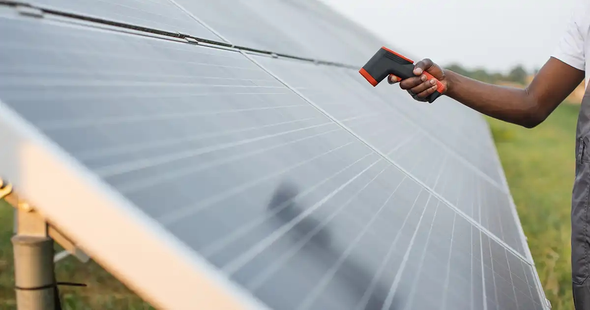
Use hydrophobic and breathable seals at frame corners to prevent moisture ingress while allowing for thermal expansion. Furthermore, regular infrared thermal imaging should be performed to detect hotspots early, and electrical performance testing should be used to quantify irreversible performance losses. During procurement, require accelerated thermal cycling and damp-heat test reports from the solar panel kit manufacturer to ensure your solar panels perform reliably.

Ensure proper installation and regular maintenance of the solar panel kit

Improving operating efficiency under high temperatures

When purchasing solar panel kits for hot climates, choose monocrystalline modules with a low temperature coefficient and thermal cycling testing. Where appropriate, consider using high-emissivity backsheets or radiative cooling films. Additionally, design a ventilated structure during installation, leaving 30-50 mm of clearance for residential applications and larger gaps for commercial use; adjust the array orientation; and finally implement a monitoring and MPPT-compatible control system to improve operating efficiency in response to thermal events.

Solar Outdoor Fan vs Traditional Outdoor Fan: Energy Savings & Environmental Impact

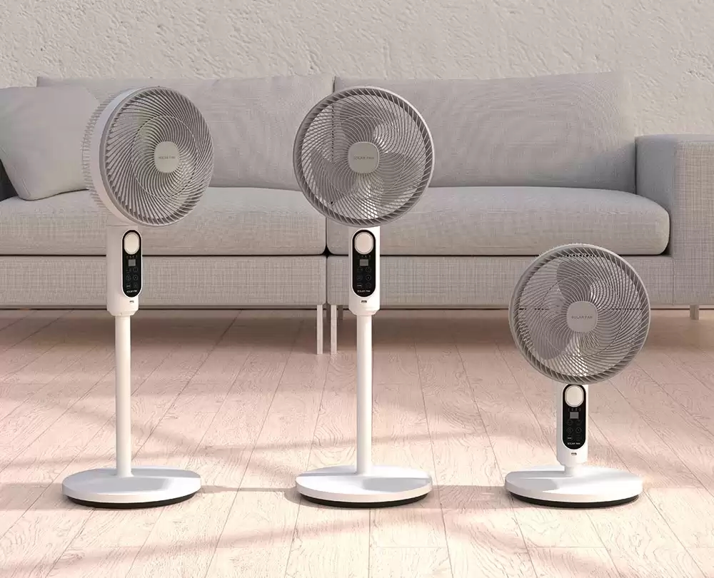
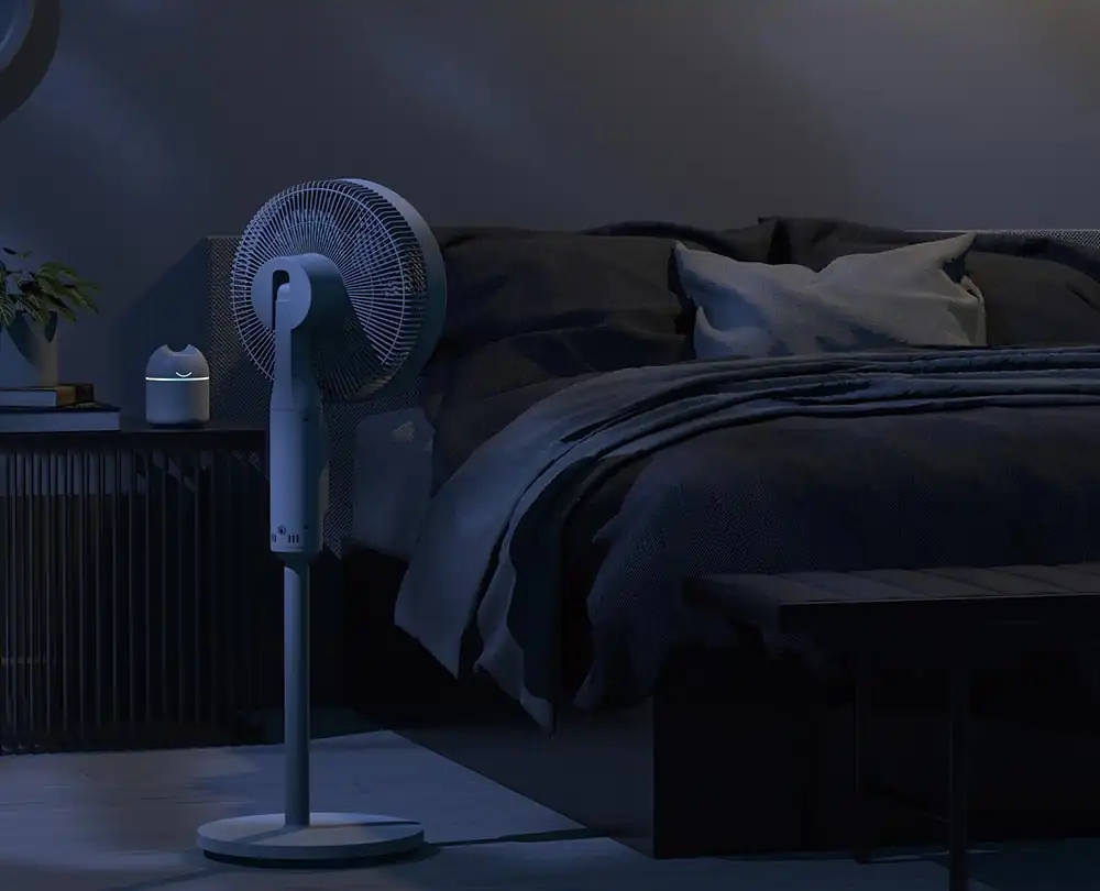
Traditional outdoor fans hum loudly while running and continuously draw power from the grid; solar-powered fans, on the other hand, silently sense when someone approaches, and their soft LED lights illuminate, increasing airflow only when someone enters their range. During the evening, a solar outdoor fan can operate without consuming any electricity. Which device would you choose to run for a season? Which one can help your brand or family achieve sustainability goals? We will answer this question through technical principles and real-world examples.

Solar Outdoor Fan with Solar and Battery Charging

A typical solar outdoor fan isn’t just a fan motor with a solar panel on the roof—it’s a complete energy system designed to capture energy from sunlight, store it, and release it in a controlled manner.

Core Components and Operation of a Solar Outdoor Fan:

Photovoltaic (PV) Modules (Solar Panels): Photovoltaic cells convert sunlight into direct current (DC) electricity. Panel size varies by model; typical home solar fans use 20-80-watt panels, depending on power and runtime requirements.

Battery Storage: Lithium-ion or lead-acid batteries store electricity for use at night or on cloudy days. Battery capacity determines the runtime.

Charge Controller/MPPT: Manages the charging process to maximize solar energy utilization, protect the battery, and prevent overcharging. Modern controllers use Maximum Power Point Tracking (MPPT) technology to improve efficiency.

Dual Charging (Solar + AC): PowerDream solar fans support both solar charging and AC power supply. This means the fan can run entirely on solar power when available, or use grid power when needed. Dual charging increases reliability and simplifies size selection.

Performance Impact:

When there is sufficient sunlight, the fan draws power directly from the photovoltaic array, while the battery is also charging. When there is insufficient sunlight, the system uses stored energy. If the battery is low or if the user requires it, the battery can be quickly recharged via AC power, or the fan can be powered directly. DC motors and appropriate controls maximize efficiency; furthermore, brushless DC motors are typically 30-50% more efficient than comparable AC induction motors used in traditional fans. In short, a solar-powered outdoor fan is an integrated miniature energy system. Its design choices, including photovoltaic power, battery capacity, motor type, and intelligent control, determine its energy independence and environmental performance.

Solar Outdoor Fan with Solar and Battery Charging

More Energy Efficient Compared to Traditional Outdoor Fans

Energy efficiency is the benefit most valued by many customers. To assess this, we compare the energy consumption over the lifecycle of a solar outdoor fan with that of a traditional outdoor fan.

Define a typical usage scenario. For example: a patio fan with a rated power of 50 watts, running 8 hours per night, 120 days per year.

Traditional fan energy consumption: 48 kilowatt-hours per season. At a US residential electricity price of $0.15/kWh, this is $7.20 per season.

Solar fan energy: If the solar fan is appropriately sized and the average daily solar power generation is sufficient to support its operation, then grid energy consumption can be zero during these periods. In this case, the operating energy cost from the grid is zero; however, implicit energy and battery charging efficiency losses must be considered.

Solar + AC hybrid operation: If the fan uses solar power during the day and only AC power during extended cloudy periods, the net grid load can be reduced by 70% to 100%, depending on battery capacity and usage patterns.

In many homes, PowerDream customers have found that replacing traditional AC fans with appropriately sized solar fans reduces daily grid energy consumption on porches and patios by 60% to 100%. Therefore, if properly sized, a solar-powered outdoor fan can eliminate most or all grid energy consumption.

Environmental Impact: Carbon Emissions, Lifecycle Analysis, and Materials

Energy efficiency means reduced environmental impact, but responsible buyers must look beyond immediate electricity consumption. A careful consideration should also include production emissions, material selection, battery life, and end-of-life recycling.

Key Environmental Factors:

1. Operational Carbon Reduction

If a solar fan saves 50 kilowatt-hours per year compared to a traditional fan, at 0.4 kg of CO2 equivalent per kilowatt-hour, this translates to approximately 20 kg of CO2 emissions per year. Over its 10-year lifespan, each fan can reduce approximately 200 kg of CO2 emissions – a significant impact when scaled up.

2. Embodied Emissions

The production of photovoltaic modules, batteries, electronic components, and metal casings all generates emissions. For small solar fans, component production accounts for the majority of embodied energy, but this proportion is relatively small compared to household photovoltaic modules.

Life cycle assessments (LCA) typically show that photovoltaic power generation devices can recoup their embodied emission costs within months to years. After recouping these costs, their net lifecycle emissions are lower than those of comparable grid-connected devices.

4. Net Environmental Conclusion:

Properly designed and deployed solar outdoor fans have a lower life-cycle carbon footprint than traditional grid-powered fans, and their operating costs can be recovered quickly. Intelligent control strategies extend battery life and enhance environmental benefits by minimizing unnecessary cycles.

Solar Outdoor Fans with Intelligent Control

Intelligent control systems are key to improving the efficiency of passive solar systems. PowerDream’s series of solar outdoor fans uses human detection technology and adaptive management features, offering three main advantages: energy savings, improved comfort, and enhanced safety.

When the sensor detects a person, the fan accelerates to a preset comfortable speed, and the lights brighten. When the sensor does not detect a person for a set period, the system dims the lights and enters an energy-saving standby mode, or reduces the fan speed. Furthermore, PowerDream integrates fan control with LED lighting. This means the fan provides both ventilation and localized lighting, enhancing the device’s value across different settings. Additionally, if solar power generation is insufficient or the battery level is low, the system can automatically request AC power assistance to ensure continuous comfort.

Solar Outdoor Fans with Intelligent Control

Delivering Real Energy and Environmental Benefits

A solar outdoor fan is more than just a highly efficient motor; it’s a miniature renewable energy system that can replace or supplement grid power, reduce carbon emissions, and improve living comfort. PowerDream’s combination of dual solar and AC charging, high-efficiency brushless DC motors, MPPT charging control, and intelligent human detection technology effectively reduces operating energy consumption, extends battery life, and delivers a hands-free, comfortable experience unmatched by traditional outdoor fans.

Frequently Asked Questions about Solar Fans

1. Can solar outdoor fans run solely on solar power, or do they always require a grid backup power supply?

A1: A properly sized solar outdoor fan can operate entirely on solar power on sunny days. PowerDream’s design supports both pure solar operation and a hybrid mode with AC power backup. To ensure continuous operation during prolonged cloudy periods, an AC backup power supply or a larger battery storage system can be used.

2. How much energy can a solar outdoor fan save compared to a traditional fan?

A2: Energy savings vary depending on location and usage. In many residential settings, a properly sized solar fan can reduce grid energy consumption by 60% to 100%. The motion sensor function can significantly reduce effective operating time, thereby multiplying energy savings.

3. Can solar fans work at night or on cloudy days?

A3: Yes – if the system is equipped with battery storage, the fan can operate at night or on cloudy days. The operating time depends on the battery capacity and the amount of solar energy collected beforehand. Solar + AC hybrid fans can use mains power when the battery is depleted.

How to Select PV Module Technology for On Grid Solar Systems: Mono vs Multi vs PERC

Suppose you have 1000 square feet of usable roof space. If you choose inefficient photovoltaic modules, you might generate only a fraction of your energy needs; if you choose high-efficiency modules, you might meet or exceed your household electricity needs and shorten the payback period. This simple trade-off is at the heart of photovoltaic module technology selection for on grid solar systems. With increasing pressure to reduce energy costs and achieve sustainability goals, the choice of module technology directly determines the system’s power generation, site suitability, and overall life-cycle economic benefits.

Component Performance and Efficiency of On grid Solar Systems

When purchasing an on grid solar system, module efficiency is the primary technical indicator you need to consider. Efficiency determines how much electricity a solar panel can generate per square foot of installed area. Monocrystalline silicon modules typically have a nominal efficiency between 18% and 22%; polycrystalline silicon modules typically have an efficiency between 15% and 17%; and PERC modules (which can be based on monocrystalline silicon cells) have slightly higher efficiency than traditional cell structures, typically improving efficiency by 1% to 2%. In practice, PERC monocrystalline silicon modules can achieve efficiencies of 20% to 22%, while standard monocrystalline silicon modules are slightly less efficient.

Why this is important for on grid systems:

Limited roof space: High-efficiency modules (monocrystalline silicon or monocrystalline PERC) maximize power generation in limited space. More kilowatt-hours (kWh) are obtained per square meter, resulting in higher system capacity per roof.

Ground-mounted or large arrays: If land is abundant, efficiency is less critical, so lower-cost polycrystalline silicon modules can be considered if capital expenditure per watt is the primary metric.

System capacity: High-efficiency modules allow you to achieve your target DC nameplate power (kWp) with fewer modules, simplifying string layout and racking installation.

In summary, for most residential and many commercial on grid solar systems, monocrystalline silicon or monocrystalline PERC modules are practical choices when the goal is to maximize roof power generation and minimize installation footprint.

Component Performance and Efficiency of On grid Solar Systems

Temperature Coefficient, Low-Light Response, and Actual Power Generation of On Grid Solar Systems

The nominal power of a photovoltaic module is not the same as its actual power generation. Two additional technical parameters, temperature coefficient and low-light response, have a particularly significant impact on power generation in practical applications.

The temperature coefficient indicates the extent to which module power decreases as the battery temperature rises. Since module batteries are typically 20-40°C above ambient temperature in the summer, a better temperature coefficient helps maintain output power at high temperatures. Monocrystalline silicon modules and PERC designs generally have slightly better temperature coefficients than older polycrystalline silicon modules. This difference becomes even more significant in hot weather. Over the course of a year, this represents a considerable difference.

Low-light performance is also important. Monocrystalline silicon cells generally perform better than polycrystalline silicon cells under diffuse light and at low sun angles in the morning and evening, thereby generating more energy on cloudy days or during periods of weak solar radiation. Therefore, if your location is hot or has high solar irradiance, prioritize module technologies with good temperature coefficients. Consider using PERC/monocrystalline cells to improve yield during high temperatures and low-light periods.

Temperature Coefficient, Low-Light Response, and Actual Power Generation of On Grid Solar Systems

Performance Degradation, Reliability, and Long-Term Warranty Considerations

On grid photovoltaic systems are a long-term investment in solar energy. Module degradation directly affects the power generation of the installed system over its lifespan, thus impacting its levelized cost of energy.

Typical degradation behaviors include:

Initial light-induced degradation: Some modules, particularly older p-type cells and some PERC variants, may experience 1-3% early light-induced degradation in the first year. Modern manufacturing processes have reduced light-induced degradation, but it still affects performance predictions.

Annual degradation rate: High-quality monocrystalline silicon modules typically have an annual degradation rate between 0.25% and 0.7%. Polycrystalline silicon modules usually degrade slightly faster. Over a 25-year warranty period, an annual degradation rate of 0.5% results in a final power output of approximately 88% of the initial rated power, while a 0.7% annual degradation rate reduces the power to approximately 82%.

For on grid solar systems, long-term reliability requires selecting modules with conservative degradation specifications, robust anti-PID design, and reputable third-party testing and certification. PowerDream’s grid-tied solar systems use field-proven monocrystalline silicon modules with conservative warranty coverage to minimize lifetime energy uncertainty for grid-tied customers.

What is PERC, and when is it relevant?

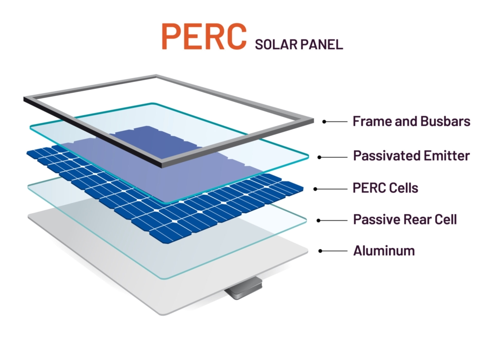
PERC is a cell-level innovation that adds a thin passivation layer to the back of the cell, reflecting otherwise lost photons back into the cell, thus improving absorption and conversion. PERC is not a different material, but rather a process upgrade applied to silicon cells—typically used in conjunction with monocrystalline silicon wafers.

Advantages of PERC for on grid solar systems:

Higher power output in the same area.

Improved low-light response and slightly improved temperature performance in many cases.

Compatibility with bifacial designs.

In some PERC designs, the likelihood of LID (light-induced degradation) or high-temperature-induced degradation is increased. Manufacturers have addressed most of these issues, but production quality and process control are important. PERC monocrystalline modules have a lower premium per watt compared to standard monocrystalline or polycrystalline modules, but this premium has narrowed as PERC has become mainstream. If you need extra watts per square meter, PERC monocrystalline silicon is an excellent choice for grid-tied systems.

What is PERC, and when is it relevant

Practical Installation Considerations and System Integration

Module technology choices also impact system design choices: string/inverter layout, tilt, mounting, shading strategies, and monitoring.

Key considerations for solar on grid system integration:

Inverter Matching: Higher-power monocrystalline/PERC modules may increase string voltage and current; ensure the inverter MPPT range, maximum input current, and series string size account for module Vmp/Voc at the coldest temperatures.

Roof Tilt and Layout: With more efficient modules, you may need fewer strings and shorter arrays, simplifying wiring and reducing BOS costs.

Shading and Mismatch: If panels face different directions, consider using microinverters or optimizers for maximum yield. Monocrystalline modules with higher shade tolerance still benefit from module-level electronics.

Bifacial Options: For ground mounts or reflective roofs, some monocrystalline/PERC bifacial modules can collect additional energy from albedo. Incorporate the module backside gain into yield models. Monitoring and Data: Choose modules that support reliable firmware and monitoring integration—on grid systems require accurate power generation data for billing and performance optimization.

PowerDream integrates monocrystalline silicon modules with appropriately sized inverters and balance-of-system components to ensure high power generation, reliable grid interaction, and predictable economic benefits.

Why Monocrystalline Silicon is the Preferred Choice for on grid Systems

Choosing photovoltaic modules for an on grid solar system means balancing efficiency, site constraints, yield over lifespan, and supplier reliability. In most residential and commercial on grid scenarios, monocrystalline modules offer the best overall value. They maximize energy per unit area, typically exhibit better temperature and low-light performance, and, when sourced from reputable on grid solar system manufacturers, offer conservative degradation rates and reliable warranties. PERC can provide a meaningful boost when limited roof space requires extra wattage, while polycrystalline silicon can still play a role when cost per watt and ample space are the dominant decision factors.

Modified Sine Wave vs. Pure Sine Wave Off Grid Solar Inverter: Which Is Better?

Choosing the right off grid solar inverter is one of the most important decisions when designing a standalone solar system. The inverter determines how the clean energy stored in the battery is converted into electricity for use by homes, tools, appliances, and outdoor systems. Currently, there are two common waveform types: modified sine wave and pure sine wave. While the difference between the two seems simple in theory, in practice, it affects equipment compatibility, efficiency, noise levels, battery stress, and long-term reliability. Therefore, I will compare the performance of the two types of off grid solar inverters under typical loads and discuss their impact on batteries and motors.

What are Modified Sine Wave and Pure Sine Wave Off Grid Solar Inverter?

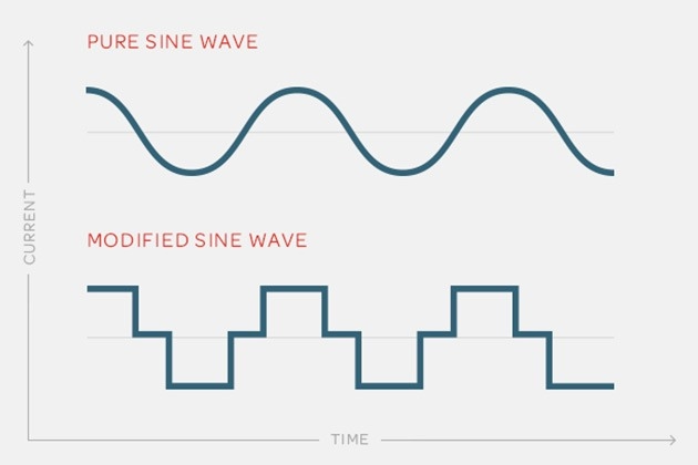
Pure sine wave off grid solar inverters produce an AC voltage waveform that is very close to an ideal sine wave – smooth, continuous, and symmetrical. This is the waveform provided by the power grid, and most household appliances are designed to operate on it. In contrast, modified sine wave off-grid solar inverters use a stepped or blocky waveform to approximate a sine wave. While this output is suitable for many resistive loads, its waveform has drawbacks: higher harmonic distortion, larger voltage transients, and less smooth current flow.

Key Practical Differences:

Harmonic Content and Total Harmonic Distortion (THD): Pure sine wave off grid solar inverters typically have lower Total Harmonic Distortion (THD), usually below 3% to 5%, while modified sine wave inverters can have much higher THD due to the larger waveform transients. Higher THD can cause motors and transformers to overheat due to waveform fluctuations.

Compatibility: Sensitive electronic devices such as computers, LED drivers, variable-speed pumps, medical equipment, and many modern household appliances require a clean sine-wave input signal. Waveform distortion can lead to malfunctions, increased electromagnetic interference, and even equipment damage.

Power Quality and Efficiency: Motors run cooler and more efficiently under a pure sine wave; audio equipment produces clear sound without buzzing; and battery charging curves are more predictable.

What are Modified Sine Wave and Pure Sine Wave Off-Grid Solar Inverters

How do the Waveform Types of the Off Grid Solar Inverter Affect Common Loads?

Different appliances respond differently to waveform quality. Solar street light controllers or LED drivers can accept modified sine waves in some cases, but many modern LED drivers and street light control units perform best with pure sine waves. Let’s analyze common off-grid loads and their performance under various inverter types.

Resistive Loads:

Modified Sine Wave: Generally acceptable. Resistive elements only dissipate power; the waveform shape has minimal impact.
Pure Sine Wave: Perfect performance. No drawbacks, but limited performance advantages compared to resistive loads.

Inductive Loads:

Modified Sine Wave: Can lead to increased heat generation, torque pulsation, increased noise, and reduced efficiency. Motor operating temperatures may be higher, shortening the lifespan. Variable frequency drives and shaded-pole motors may malfunction.
Pure Sine Wave: Smooth torque, low heat generation, and normal efficiency. Crucial for water pumps, washing machines, and HVAC compressors.

Sensitive Electronic Equipment:

Modified Sine Wave: Risks of improper operation, false alarms, or damage. Some power supplies may generate extra heat or reject the waveform.
Pure Sine Wave: Ensures safe and reliable operation of switching power supplies and electronic control equipment.

How do the Waveform Types of the Off Grid Solar Inverter Affect Common Loads

Battery Life, Charging Characteristics, and System Efficiency

One of the core objectives of off grid system design is to maximize the energy utilization of the battery bank. Off grid solar inverters are a critical component of off grid solar systems, influencing charging methods, discharge depth patterns, and overall energy efficiency.

Impact on Charging and Battery Cycling:

Modified sine wave inverters sometimes employ simpler control electronics, which can lead to reduced accuracy in charging and control signals. When integrated with the inverter’s charger, this can result in irregular charging algorithms, increasing cycle efficiency losses. Pure sine wave off grid solar inverters are typically compatible with BMS-enabled chargers, temperature compensation, and multi-stage constant-current/constant-voltage/float charging. More efficient charging methods better protect battery health and reduce premature capacity degradation.

Efficiency and Heat Loss:

The current drawn by motors and appliances varies with the waveform; changing the waveform typically increases the RMS current for the same load, thereby increasing I²R losses in the wires and internal components. This loss manifests as heat, reducing the battery’s net usable energy. Pure sine wave off-grid solar inverters produce a smoother current waveform and typically incorporate high-efficiency topologies (e.g., high-frequency transformers or transformerless designs), resulting in higher conversion efficiency and lower standby losses.

Long-Term Battery Life Impact

Because pure sine wave off grid solar inverters reduce unnecessary heat generation in the load and enable more precise charge control, the battery pack experiences fewer stress cycles and more predictable state-of-charge management. Over the system’s lifespan, this can significantly save on battery replacement costs and downtime—especially critical in off-grid applications where reliability is paramount.

At PowerDream, we use off grid solar inverters with pure sine-wave output to optimize charging algorithms and minimize parasitic losses, thereby preserving battery cycle life and maximizing overall system round-trip efficiency.

Reliability, Diagnostics, and Field Performance

When a system is off grid, remote reliability is crucial. Failures not only incur repair costs but often lead to reduced productivity or comfort. Modified sine wave off grid solar inverters are typically simpler in design but can impose higher thermal and electrical stress on connected equipment. These downstream stresses increase the probability of field failures. Pure sine wave off-grid solar inverters, with robust thermal management, conservative component derating, and active fault detection, prevent catastrophic failures.

In terms of system monitoring and diagnostics, pure sine wave off grid solar inverters typically include a range of telemetry and diagnostic features—fault logging, remote alarms, and historical energy graphs—that expedite troubleshooting of remote installations. Lower-priced modified sine wave units may lack comprehensive telemetry capabilities, resulting in slower, more costly fault isolation. Regarding field performance, off-grid systems often operate in harsh environments. Off grid solar inverters designed for these environments feature conformal coatings, higher ingress protection ratings, and dust-resistant cooling systems. These design choices reduce downtime and extend the mean time between failures. For critical applications such as telecommunications equipment rooms, medical clinics, or remote streetlights, PowerDream recommends using off-grid inverters with pure sine-wave output, as they provide predictable performance.

Reliability, Diagnostics, and Field Performance 1

Why use pure sine wave off grid solar inverters?

Considering overall performance, efficiency, reliability, and long-term economics, pure sine wave off grid solar inverters are the better choice for most practical off-grid applications. While modified sine wave inverters have advantages in certain specific applications, such as when cost is the primary consideration and the load is purely resistive, off-grid ecosystems include smart LEDs, inverters, water pumps, and precision electronic equipment that require a clean, stable AC waveform. Pure sine wave inverters reduce electromagnetic interference (EMI), lower motor operating temperatures, extend battery life, and minimize unexpected failures. Furthermore, they simplify integration with telemetry systems and modern battery management systems.

How to Verify the Quality of Lithium Ion Solar Battery?

As a lithium ion solar battery supplier with years of experience, we have encountered a wide range of lithium ion solar battery quality-related failures—from residential off-grid homes to commercial solar projects. 68% of lithium-ion solar battery failures stem from uncertified production or exaggerated cycle-life claims, and 42% of users lose thousands of dollars due to poor battery quality, resulting in downtime, repairs, or replacements. This guide will focus on two of the most critical checks: CE/UL certification and cycle life verification, explaining their importance, implementation methods, auxiliary quality tests, and PowerDream’s rigorous quality control processes.

Safety Compliance Certification for the Lithium ion Solar Battery

Certification is the primary indicator that a lithium ion solar battery has passed independent safety and performance testing. However, not all certifications are equally valid.

Key Certification Meanings:

CE (Europe): Indicates compliance with EU safety and electromagnetic compatibility requirements. For batteries, the CE mark indicates that the manufacturer has met the relevant EU directives.

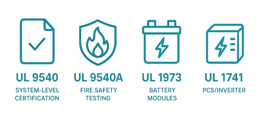
UL (North America): Crucial for the United States and Canada. UL certification covers multiple battery standards: UL 1642 (cells), UL 1973 (batteries for stationary applications), and UL 9540/UL 9540A (energy storage systems and fire resistance testing). UL certification typically includes factory inspections and ongoing compliance checks.

IEC Standards: International standards such as IEC 62619, IEC 62133, and IEC 62933 are crucial in many markets.

UN38.3: A necessary condition for the transportation of lithium batteries. Passing the UN38.3 test means the battery can withstand various risks commonly encountered during transportation (altitude, temperature, vibration, shock).

TÜV/CE, RoHS, REACH: Additional markings for chemical compliance and restricted substances may be related to environmental and import regulations.

How to verify certificates? You can request test reports and certificates with laboratory markings from lithium-ion solar battery suppliers. Authoritative certificates should include the issuing laboratory name, report number, and test date. Verification with the issuing body is also possible. Many laboratories list issued certificates in searchable databases. For UL certification, use the UL online certification database to verify your product or component’s certification information.
Additionally, check the certification scope and model. CE or UL certificates should list the exact part number, rated capacity, and configuration. If a certificate only covers the “battery type” and not the assembled module, it is incomplete for an installed system.

Safety Compliance Certification for the Lithium ion Solar Battery

Cycle Life Testing of the Lithium ion Solar Battery

Cycle life determines long-term economic benefits. When suppliers claim “10,000 cycles,” they usually mean “X cycles to achieve Y% capacity under specific conditions.” Therefore, always carefully read the terms and conditions and request concrete evidence from the supplier.

Key Concepts of Cycle Life

Cycle Count: One complete discharge and charge cycle. Manufacturers typically report the number of cycles to reach 80% of rated capacity, which is the industry benchmark.

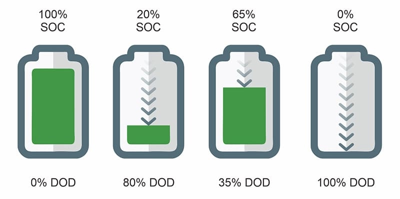
Depth of Discharge (DoD): The depth of discharge of the battery per cycle. 100% depth of discharge degrades the battery faster than 80% or 50% does. Cycle life is closely related to depth of discharge.

C-rate: Refers to the charging/discharging rate. A higher C-rate increases battery stress and shortens cycle life. Typical household battery specifications use a C-rate range of 0.2C to 1C.

Temperature: High temperatures accelerate capacity decay. Cycle life is usually determined under ambient testing temperatures.

How to interpret claims representing cycle life? First, we can look at the test conditions. A specification like “10,000 cycles” is meaningless without information such as the depth of damage (DoD), the cycle rate (C-rate), and the temperature. Ask for details of the test protocol, such as: “10,000 cycles to 80% DoD at 25°C, in 0.5°C increments.” Some reputable suppliers provide cycle-to-remaining-capacity curves that show how capacity decays over time. Examine where and under what conditions the 80% capacity degradation point occurs. Also, consider the chemical composition: lithium iron phosphate (LFP, LiFePO₄) typically offers a longer cycle life and better heat dissipation.

Cycle Life Testing of the Lithium ion Solar Battery

Supplementary Quality Testing for Lithium ion Solar Batteries

CE/UL certification and cycle life are the foundation of quality verification, but not the whole story. The following three supplementary tests ensure your lithium ion solar batteries operate reliably in a real-world solar system:

1. Capacity Retention Test

Capacity retention measures how much of a battery’s initial capacity it retains after many years of use. A high-quality lithium-ion solar cell should retain more than 80% of its rated capacity after reaching its rated cycle life. Therefore, you can request annual capacity retention data—PowerDream batteries retain 90% capacity after 1 year of use, 85% after 5 years, and 82% after 10 years.

2. Battery Management System Quality

The BMS is the “brain” of a lithium ion solar battery, responsible for regulating charging and discharging, preventing overheating, and balancing battery voltage. A poor-quality BMS can cause premature battery failure. Check the following:

Cell Balancing: Ensures all cells in the battery pack charge and discharge evenly (preventing weaker cells from dragging down overall performance). Thermal Monitoring: Shuts down the battery when the temperature exceeds 140°F (60°C) (crucial in hot climates). Overcharge Protection: Stops charging when the voltage exceeds the safe range (prevents battery swelling and fire). PowerDream tests each BMS to ensure it meets UL 1973 standards.

3. Temperature Performance

Lithium-ion solar cells perform poorly at extreme temperatures—unless specifically designed for this. Request temperature performance data:

Cold Weather: High-quality batteries retain over 80% of their capacity at 32°F (0°C) (a standard winter temperature). Inferior batteries will drop to 50% capacity at this temperature. Hot Weather: Retains over 85% of its capacity at 104°F (40°C) (a common summer temperature). Our batteries employ a thermal management system that maintains performance at temperatures up to 140°F (60°C).

PowerDream’s Four-Step Quality Validation Process

PowerDream’s lithium ion solar battery quality verification is conducted at every stage of production. Furthermore, our four-step process ensures that every cell meets CE/UL standards, achieves its expected cycle life, and operates reliably and stably in real-world environments. As a result, 99% of our customers have not reported any quality issues.

Step 1: Raw Material Testing

We only source Grade A lithium ion batteries and test them for the following: Capacity consistency. Cycle life (batteries undergo 500 cycle tests to ensure they meet our 10,000-cycle battery pack rating). Safety (batteries undergo short-circuit and overcharge tests to ensure they do not overheat).

Step 2: Battery Management System (BMS) Integration and Testing

We perform cell balancing tests to ensure all cells charge and discharge evenly. Then, we conduct thermal monitoring tests to assess their response under extreme temperatures. Next, fault detection is performed to ensure the BMS shuts down the battery in case of overcharge/short circuit. Step 3: Cycle Life and Capacity Testing. Each batch of lithium-ion solar cells undergoes 1000 cycle tests to verify capacity retention.

Step 4: Safety and Compliance Testing.

We conduct CE (IEC 62133) and UL 1973 compliance testing on each lithium ion battery to ensure thermal stability, shock resistance, and overcharge protection. Step 5: Final Inspection and Documentation. Each lithium-ion solar cell undergoes visual inspection and final capacity testing. We also provide a comprehensive quality report for each order.

Supplementary Quality Testing for Lithium ion Solar Batteries

Field Performance, Commissioning, and Continuous Monitoring.

Quality verification continues after purchase. Proper commissioning and monitoring ensure the system operates as expected under real-world conditions.

Commissioning checks require charge-discharge testing of the installed system to verify that its initial usable capacity matches the nameplate reading. A practical acceptance test might involve controlled 0.5 °C discharge under specific conditions. Additionally, a battery management system (BMS) and communication verification are required to ensure the system can report state of charge (SOC), state of health (SOH), temperature, and alarm information, and store logs for warranty verification.

Simultaneously, thermal analysis is performed using thermal imaging technology to detect hot spots in battery cells, connection points, and buses during commissioning. Continuous monitoring and remote diagnostics are also necessary; PowerDream provides a remote SOH control panel and issues alerts when battery aging exceeds expectations.

Certification and Cycle Life are Important Benchmarks

The performance of lithium ion solar batteries depends on their quality. Quality verification is not complicated—it boils down to two indispensable checks: CE/UL certification ensures safety and compliance, and cycle life verification ensures long-term durability. Furthermore, the quality, temperature performance, and manufacturing standards of the battery management system (BMS) must be checked to avoid the costly mistakes that plague 68% of solar energy users.

Market trends and technological advancements in the home solar energy system

In many countries and regions today, rooftops are more than just shelter from the elements—they also collect energy, reduce utility bills, and stabilize the power grid. Over the past decade, the home solar energy system has transformed from a niche green option to a mainstream home investment. Data shows that falling panel costs, improved energy storage economics, and more intelligent electrification are driving this adoption. As a home solar system manufacturer, I see three forces shaping this market: economic, technological, and policy factors.

Market Adoption and Economic Drivers of Home Solar Energy System

Driven by falling costs, rising retail electricity prices, and increased public awareness of energy independence, the adoption of home solar energy systems continues to grow globally and across the United States. Key market drivers include: declining component prices, with monocrystalline PERC and N-type technologies lowering the cost per watt; improved balance-of-system efficiency; and financing innovations such as solar loans, power purchase agreements (PPAs), and leases, which reduce the barrier to entry for upfront costs. Furthermore, utility rate structures, particularly time-of-use (TOU) pricing, increase the value of solar-plus-storage systems by allowing homeowners to shift generation to peak pricing periods. Meanwhile, corporate and municipal commitments to decarbonization, along with local incentives, continue to stimulate residential solar system deployment.

From a manufacturer’s perspective, economies of scale and standardized designs reduce installation costs, while differentiated services—warranties, performance guarantees, and monitoring—become competitive advantages. For homeowners, the result is clear: in many US markets, an appropriately sized and installed home solar system can typically pay for itself within 5-10 years, while also increasing property value and reducing reliance on the grid.

Market Adoption and Economic Drivers of Residential Solar Systems

Photovoltaic Module Innovations and Panel Efficiency Trends in the Home Solar Energy System

One of the most significant technological advancements in home solar systems is the rapid improvement in photovoltaic module efficiency and reliability. Monocrystalline technologies, including PERC, bifacial, and heterojunction (HJT) cells, have increased module efficiency, while many high-end panels maintain long-term degradation rates of less than 0.5% per year. New N-type cell technology and TOPCon structures further reduce recombination losses and improve module efficiency. Bifacial modules and frameless designs can collect reflected light, resulting in slightly higher energy generation per unit of rated power on specific roof types.

For homeowners, higher-efficiency panels mean fewer components are needed for the same capacity, resulting in less roof space occupied—which is especially important for roofs with limited area or shading. Furthermore, some manufacturers of home energy solar systems are improving reliability by enhancing encapsulation materials and using thicker glass to reduce microcracks and potential-induced degradation. These component-level improvements allow designers to deliver greater system capacity within the same roof area, thus increasing annual electricity generation.

Photovoltaic Module Innovations and Panel Efficiency Trends in the Home Solar Energy System

Energy Storage and Battery Integration Trends

The inclusion of home energy storage is transforming the value proposition of home solar systems. Lithium-ion batteries remain the dominant technology for home energy storage due to their high energy density, decreasing costs, and reliable performance.

Recent trends include integrated inverter-battery systems for simplified installation; AC-coupled and DC-coupled storage topologies suitable for retrofit and new-construction projects, respectively; and increased use of secondary battery technologies to achieve circular-economy benefits. Improvements in battery chemistry and economies of scale have reduced the cost per kilowatt-hour, making energy storage economically viable for many homeowners.

Energy storage enables self-consumption, backup power during outages, and time-of-use shifting to avoid expensive peak-hour electricity rates. Software also plays a crucial role, with intelligent energy management systems (EMS) optimizing charging and discharging times based on weather forecasts, electricity price signals, and user preferences. For homes in areas prone to fires or power outages, combining solar with battery backup power enhances system resilience. It can be a decisive factor in choosing a home solar system.

Inverters, Power Electronics, and Grid Interaction

Inverters and power electronics are critical to the performance of a home energy solar system and its interaction with the grid. Technological advancements are primarily evident in three areas:

1. Smarter grid-tied inverters capable of advanced functions such as voltage-reactive power support and fault ride-through; the application of microinverters and power optimizers; and integrated hybrid inverter architectures.

2. Grid-tied inverters support new utility projects and facilitate the widespread adoption of rooftop solar systems by providing reactive power support and frequency response. Microinverters and DC optimizers maximize energy harvesting efficiency on partially shaded or complex-roofed homes by independently managing each component. At the same time, initial purchase costs are higher, but they typically increase energy yield and simplify system expansion.

3. Hybrid inverters reduce the number of components in combined PV and battery storage systems and enable features such as stacked storage, flexible islanding operation, and firmware upgrades. For homeowners, choosing the exemplary inverter architecture depends on roof shape, shading conditions, storage plans, and desired grid services.

Smart Home Integration, Monitoring, and Digital Services

Home solar systems are increasingly integrated into the broader smart home ecosystem. Monitoring platforms now provide real-time generation, consumption, and battery level data, accessible via mobile apps and cloud dashboards. Beyond basic monitoring, innovative energy management platforms enable automated load shifting, EV charging coordination, and demand response participation, monetizing flexible loads. Data analytics and predictive maintenance utilize component-level data and weather forecasts to prevent failures and schedule cleaning.

Furthermore, software enables Virtual Power Plant (VPP) participation, where aggregated residential systems can provide grid services and receive incentives. For homeowners, these digital services mean convenience, reduced O&M costs, and potential additional revenue streams. Privacy, cybersecurity, and interoperability standards remain important considerations when deploying cloud-connected energy devices.

Home Solar System Smart Home Integration, Monitoring, and Digital Services

Installation Trends, Design Optimization, and Permitting Streamlining

Home solar system installation methods are evolving to increase energy yield and reduce soft costs. Standardized racking and pre-assembled system balance-of-system kits reduce rooftop labor time. As a result, there is a growing trend towards roof-integrated solar systems and low-profile rail systems that improve aesthetics and reduce wind loading. Additionally, site modeling tools, drone mapping, and 3D shading analysis simplify the design process and enable accurate energy yield estimates before construction.

In some regions, permitting and interconnection delays remain significant obstacles; however, digital permitting processes and streamlined standards are shortening installation times in some advanced cities. For retrofit projects, AC-coupled storage kits and microinverter solutions reduce complexity and avoid running DC wiring through the house. For designers, the focus remains on maximizing power generation per unit of roof area, optimizing string design to cope with shading, and minimizing interference with future expansion.

Future Trends in the Home Solar Energy Storage Industry

Home solar energy systems are becoming increasingly mature, evolving into a flexible and reliable home energy solution. Market trends show a growing adoption of home solar systems, driven by economic benefits and incentives, while technological advancements are enabling more efficient solar panels, integrated energy storage systems, smarter inverters, and higher-quality digital services.

Installation Guide to Monocrystalline Solar Panels for Roofs: Orientation (South/East/West) Matching

A correctly oriented and installed monocrystalline solar panel array can convert solar energy into stable, clean energy. In many climates, a well-positioned rooftop solar panel array can meet 15% to 25% of a home’s annual electricity needs per kilowatt of installed capacity; the actual figures will vary depending on latitude, shading, and orientation, but the key is that small design decisions during installation will ultimately accumulate into significant differences in energy production over the system’s lifespan. This guide will show you how to select, install, and configure monocrystalline silicon solar panels on your roof, including assessing your roof, choosing a south-facing or east-west layout, and matching strings and inverters to maximize output and reliability.

Monocrystalline Solar Panels: Starting with Roof Assessment and Site Survey

Before selecting monocrystalline silicon solar panels or signing permits, be sure to conduct a systematic assessment of your roof. The best installation orientation decisions begin with a reliable understanding of the site conditions.

Key information to record:

Roof Orientation: Measure the azimuth angle of each central roof plane. South-facing roofs in the Northern Hemisphere have an azimuth angle of 180°. A compass app can be used, or a surveyor can be hired for more precise measurements.

Roof Pitch: Standard residential roofs have a pitch ranging from 10° to 45°. The pitch interacts with the orientation to determine seasonal yield.

Available Area: Map the unobstructed area of ​​each roof plane, considering vents, skylights, chimneys, and setback requirements.

Shading Analysis: Conduct a year-long shading study. Short-term inspections can capture noticeable shading, but simple shading tools or smartphone apps can reveal seasonal obstructions.

Structural Load Capacity: Confirm that the roof structure can support the additional dead and live loads. Most modern roofs can support a standard PV array, but older roofs may require reinforcement.

Monocrystalline Solar Panels 1(1)

Installation Options for South-Facing Monocrystalline Solar Panels

For most roofs in the Northern Hemisphere, south-facing is the default recommended installation direction. Installing solar panels facing south allows them to absorb the maximum amount of daily sunlight throughout the year, thus typically maximizing annual power generation.

Advantages of South-Facing Orientation:

With the correct tilt angle, south-facing arrays often produce the most energy annually because they receive balanced sunlight in both the morning and afternoon. Furthermore, system sizing is easier, and real-time shading decisions are simpler.

Practical Orientation and Tilt Rules:

If you live in a mid-latitude region (e.g., 30° to 40° North latitude) and want the highest annual energy output, the tilt angle should be close to or slightly less than your latitude (latitude minus 10° to latitude). If winter production is more important, increase the tilt angle by about 10°; if summer production is more important, slightly decrease it. Installation is both more straightforward and more aesthetically pleasing when the roof slope matches the desired tilt.

Installation Options for South-Facing Monocrystalline Silicon Solar Panels 1

When can separate east-west installations provide greater value?

East-west layouts are not a secondary option, but a strategic one. When roof geometry or obstructions limit south-facing monocrystalline silicon solar panel installations, orienting panels east and west can provide greater value.

Why choose East-West?

Because it provides a wider production curve, the east side is better for morning power generation, and the west side is better for afternoon power generation. An east-west side-by-side layout produces a flatter daily power generation curve and better matches morning and evening peak electricity demand. Also, many residential roofs have large east-west-facing planes. Utilizing these two planes can increase the total area of ​​solar panels and power generation. Furthermore, if trees or chimneys shade the south side, but the east and west sides remain unobstructed, utilizing the east and west sides is practical and often more effective.

Design Tips for East-West Arrays:

Use matched strings: Group east-facing modules together and west-facing modules together to avoid string mismatch issues in case of partial shading. Ideally, each orientation should have its own MPPT input on the inverter. Consider the inverter structure: Microinverters or DC optimizers perform well in east-west installations because they can manage panel-level power mismatches and extract more energy from mixed orientations. If using string inverters with single maximum power point tracking,

Tilt angle is essential: A moderate tilt angle should be maintained for east-west orientations, as the sun is lower on the horizon in the morning/afternoon, and a steep tilt angle will reduce the angle of incidence.

Energy efficiency: An east-west balanced layout typically results in slightly lower annual energy consumption than an optimal south-facing layout, but in cases where peak electricity demand occurs during off-peak hours or roof area is limited, an east-west layout can improve overall system efficiency.

When can separate east-west installations provide greater value

Roof Array Tilt, Spacing, and Row Matching

Orientation is only half of what affects solar panel installation performance; tilt angle and array spacing also significantly impact annual energy generation and system reliability. For rooftop monocrystalline silicon solar panel installations, these geometric parameters are often constrained by roof slope and available area; if adjustable, they should be deliberately set.

Tilt Guidance:

Based on latitude rules, a standard baseline tilt angle for balanced performance throughout the year equals the latitude, which can be adjusted by ±10° depending on seasonal needs. When the rack tilt angle does not match the roof slope, wind load, and structural load requirements must be confirmed. Low-friction tilt frames (10°–15°) can also be used to balance performance with wind load and maintenance access.

Row Spacing:

Avoid self-shading: When panels are tilted, the upper monocrystalline solar panels may shade the lower panels in the early morning during winter; increasing spacing appropriately can reduce energy loss. For single-layer rooftop PV systems, spacing is less of an issue. Still, if you are installing multiple layers of panels or elevated frames, you need to calculate the spacing to prevent winter shading.

Service Space: Maintain minimum clearance required for cleaning and fire escape. Many regions have requirements for walkway width or edge clearance.

Matching Panels and Strings:

Maintain a consistent electrical group configuration: combine panels of the same brand/model and orientation into the exact string. Mixing panels with different tilt angles/azimuths in the precise string will lead to mismatch losses. Paired panels should maintain a consistent tilt angle. If the modules in the exact string have uneven tilt angles, the string’s performance will depend on the module with the smallest tilt angle. Maintain consistent panel geometry within each string.

Electrical Matching and Inverter Selection

Matching orientation and the electrical aspects of panels may sound technical. Still, the key points are simple: minimize mismatches, use the correct inverter approach, and plan for the long term.

Two common inverter strategies:

Single Maximum Power Point Tracking (MPPT) string inverter: Best suited for arrays with consistent orientation. It is cost-effective but more sensitive to orientation deviations.

String inverter with multiple MPPTs: Allows you to connect east-facing solar panel strings to one MPPT and west-facing strings to another. This is a good option for roofs with asymmetrical orientations.

Practical Matching Rules:

Ensure the string voltage is within the inverter limits; installers will design the strings based on the inverter’s input voltage range. This limits the number of modules per string, but it’s standard practice. Also, allocate MPPTs by direction: if the inverter has two MPPT inputs, one for south/east and the other for west or different tilt groups. Prioritize designs that facilitate monitoring: choose inverters with module-level monitoring to quickly identify underperforming modules.

Adjust Installation Orientation Based on Goals and Document All Information

The choice of orientation for rooftop monocrystalline solar panel systems is not a simple either/or decision. In many regions, south-facing arrays maximize annual energy production. Still, when roof geometry, shading, or electricity usage patterns are better suited to morning or evening generation, east-west or split layouts often yield higher returns. The right choice depends on three factors: a reliable site survey, a clear understanding of electricity load and tariff structures, and a power solution that minimizes mismatches.

Aluminum Alloy Solar Mounting System: Lightweight & High-Strength for Easy Installation

When evaluating the efficiency of solar power systems, most people focus on the conversion rate of solar panels or the stability of inverters, neglecting a critical component that directly affects system lifespan and operational efficiency: the solar mounting system. According to data from the International Renewable Energy Agency (IRENA), poorly performing solar mounting systems can reduce overall power generation efficiency by 5%-15% and shorten the lifespan by more than half. This is precisely where PowerDream, as a professional solar product manufacturer, excels. Our solar mounting system is made of aluminum alloy and stainless steel (A2-70, SUS304/410). These systems not only address common pain points of traditional brackets, such as heavy weight, difficult installation, and susceptibility to corrosion, but also achieve a perfect balance between lightweight design and high strength, ensuring a stable service life of 20-25 years, even in harsh environments.

Aluminum Alloy: The Lightweight Material in Solar Mounting System

Material selection is fundamental to high-quality solar mounting systems, and aluminum alloy stands out among many materials due to its unique properties. Unlike traditional steel brackets, which are prone to rust and heavy, PowerDream solar mounting systems use high-purity aluminum alloy that undergoes rigorous heat treatment and surface anodizing. This material has a density of only 2.7 g/cm³, which is 35% of carbon steel, making the entire solar mounting system significantly lighter.

For example, a mounting system for a 10kW rooftop solar project weighs only 300-400kg, while a traditional steel system of the exact specifications weighs 800-1000kg. This lightweight advantage is particularly evident in rooftop installations: it can reduce the load-bearing pressure on the building’s roof by more than 50%, eliminating the need for additional roof reinforcement and saving significant construction costs and time. At the same time, the anodized layer on the aluminum alloy brackets is more than 10 μm thick, effectively resisting oxidation, acid rain, and salt spray corrosion, making it suitable for harsh environments such as coastal areas, industrial zones, and high-altitude regions.

Aluminum Alloy The Lightweight Material in Solar Mounting Systems

Hybrid Design with Stainless Steel for High Strength

Lightweight design does not mean sacrificing strength. To further enhance the system’s structural stability, we use a hybrid design combining an aluminum alloy with high-quality stainless steel components. Power Dream makes key stress points—such as connecting bolts, nuts, and fasteners—from stainless steel materials that meet international standards, including A2-70 stainless steel for general applications and SUS304/SUS410 stainless steel for high-corrosion, high-load environments. A2-70 stainless steel has a tensile strength of up to 700 MPa, twice that of ordinary steel bolts, ensuring a strong, reliable connection between the solar mounting system and the roof or ground and preventing loosening.

In addition, we have optimized the structural design of the aluminum alloy beams and columns by using a hollow-section design, increasing bending and torsional strength by 30% while reducing weight. Through rigorous mechanical performance testing, the PowerDream solar mounting system can withstand a maximum wind load of 60 m/s and a maximum snow load of 1.2 kN/m², meeting the installation requirements of different climate zones worldwide.

How does the solar mounting system save 50% of construction time?

For solar project contractors and installers, the installation efficiency of the solar mounting system directly affects project progress and labor costs. PowerDream has fully considered this need in the product design process and created a modular, pre-assembled solar mounting system. First, all system components, including aluminum alloy beams, columns, clamps, and stainless steel fasteners, are pre-processed and numbered at the factory. Installers only need to assemble them according to the installation manual, eliminating the need for on-site cutting, welding, or drilling, significantly reducing the difficulty of on-site construction.

Secondly, we have designed a quick-connect structure for the key components of the solar mounting system: the beams and columns use an insert-type connection design with locking bolts, which can be fixed with a simple wrench, and the installation time for a single connection point is less than 1 minute. Compared with traditional steel mounting systems that require on-site welding and rust prevention treatment, PowerDream’s system can save more than 50% of installation time.

How does the solar mounting system save 50% of construction time

20-25 year service life, more reliable durability

Traditional steel solar mounting systems typically have a service life of 10-15 years, and problems such as rust, deformation, and loose connections often occur after 5-8 years, requiring frequent maintenance and replacement, thereby increasing the project’s operating and maintenance costs. In contrast, PowerDream manufactures solar mounting systems from high-quality aluminum alloy and stainless steel, follows rigorous manufacturing processes, and designs them for a service life of 20–25 years, perfectly matching the lifespan of solar panels. Authoritative third-party testing confirms this: after 3000 hours of salt-spray corrosion testing, the aluminum alloy brackets showed no significant corrosion and their mechanical properties remained unchanged; after 10,000 fatigue vibration tests, the system connection points remained secure, with no signs of loosening or deformation.

For users choosing solar projects, selecting PowerDream’s solar mounting systems means no need to replace brackets over the entire lifespan of the solar system, significantly reducing operational and maintenance costs.

Roof, Ground, and Floating Solar Mounting System

Different photovoltaic installation scenarios have different requirements for photovoltaic mounting systems. PowerDream has launched a series of targeted products to meet the diverse needs of its customers. For rooftop photovoltaic projects, we have designed a lightweight bracket that does not require roof penetration: we fix the base to the roof using counterweights or vacuum suction cups, avoiding damage to the roof’s waterproofing layer, and we adjust the bracket’s angle based on local latitude to maximize solar energy utilization.

For ground-mounted photovoltaic projects, we have developed pile-driven and concrete foundation support systems: professional equipment is used to drive piles into the ground, and the depth of the piles is adjusted according to geological conditions to ensure system stability. Additionally, for floating photovoltaic projects on lakes, reservoirs, and other bodies of water, we use a combination of corrosion-resistant aluminum alloy frames and high-density HDPE pontoons. This structure not only provides excellent buoyancy but also effectively resists corrosion from water and microorganisms. Whether on residential rooftops, large industrial plants, desert ground, or water surfaces, PowerDream can provide customized photovoltaic mounting system solutions to ensure stable operation in various scenarios.

Roof, Ground, and Floating Solar Mounting Systems

The Foundation of High-Efficiency and Durable Solar Systems

In the entire solar power system, the solar mounting system is far more than just an accessory; it is the solid foundation that ensures long-term, efficient, and stable operation. While many users are preoccupied with improving solar panel conversion efficiency and neglecting the potential risks posed by inferior brackets, PowerDream has already developed a comprehensive bracket installation solution built on aluminum alloy and stainless steel. It not only solves the pain points of traditional mounting systems—such as heavy weight, complex installation, and short service life—but also incorporates advantages such as a lightweight design (reducing roof load by 50%), high strength (withstanding strong winds of up to 60 meters per second), and a modular design, ensuring reliable conversion of your solar energy into value.

How to solve the grid compatibility problem of a grid connected solar system?

A homeowner who installed a 15kW grid-connected solar system by a local contractor experienced a grid outage that not only failed to reduce electricity bills but also crippled his refrigerator, grill, and POS system. The power company stated that the solar inverter was incompatible with the grid, causing unstable voltage and triggering their safety switches. Many grid connected solar system users encounter grid incompatibility issues. On average, each incompatibility-related outage costs businesses significant money, and 22% of homeowners face fines from utility companies for non-compliant systems. As a grid-connected solar system manufacturer, I will explain how to address the grid compatibility issues that plague these systems, ensuring your solar system and the grid work in harmony.

Problems Caused by Grid Incompatibility of Grid Connected Solar System

Many solar buyers believe that “compatibility” is merely a technical afterthought that the installer will handle. However, grid connected solar systems do not exist in isolation; they are intricately connected to the local power company’s grid, and even minor mismatches can lead to catastrophic failures.

The first is unplanned power outages. The power grid relies on stable voltage (120V/240V for residential, 480V for commercial) and frequency (60Hz in the US). A mismatched inverter will supply unstable power to the grid, triggering the power company’s protective relays to disconnect. This is because the inverter cannot handle the frequent voltage spikes in the state. Secondly, it will result in energy savings losses. Incompatible systems often operate less efficiently or shut down during peak sunlight hours. Thirdly, there are power company fines and legal risks. All US power companies have strict grid connection standards for grid-connected solar systems (defined by the IEEE 1547 standard). Non-compliant systems will face fines and may even be disconnected entirely. Fourthly, it can damage equipment. Voltage mismatch can burn out solar panels, inverters, and even your business’s electrical equipment.

What we need to understand is that not all grid-connected solar systems work on all grids. Instead, you need a system designed specifically for your grid, not a “works for any grid” system.

Problems Caused by Grid Incompatibility of Grid Connected Solar System (1)

Three Core Compatibility Issues of Grid Connected Solar System

Compatibility issues don’t happen by chance—they stem from four predictable gaps between the solar system and the grid.

1. Voltage and Frequency Mismatch

Grid voltage and frequency fluctuate slightly, but your inverter must match these changes in real time. If the grid voltage is 118V and the inverter outputs 125V, the grid’s relays will trip. Signs of this problem:

The system shuts down during peak sunlight. Your home/office lights flicker when the solar system is on. Your power company notifies you of a “voltage anomaly.” Cause: Ordinary inverters use a “fixed” voltage setting, not an “adaptive” one. PowerDream’s grid-connected inverters use grid tracking technology, adjusting voltage and frequency 100 times per second to match your power company’s specifications.

2. Anti-Islanding

Anti-islanding is a safety feature that shuts down your on grid solar system during a grid outage. This prevents the formation of an “island” of power that could potentially electrocute repair personnel. All power companies require anti-islanding devices, but many inexpensive systems use defective devices. For example, the system continues to operate during grid outages, and the power company rejects your grid connection application, citing “insufficient safety features.” The inverter displays an “anti-islanding failure” code. This is because low-quality equipment uses outdated “passive” detection methods, missing many outages.

3. Communication Protocol Defects

Your grid-connected solar system needs to communicate with the power company for net metering and remote monitoring. If the protocols of both parties are incompatible, you will not be able to save costs or understand your electricity usage. Signs of incompatibility include:

The power company cannot track your remaining electricity consumption—therefore, you will not receive net metering subsidies. You cannot view the system’s output or grid status in the power company’s application. The power company requires you to perform a “protocol upgrade” after installation. This is because the power company uses a different protocol. Systems designed for Modbus are incompatible with power companies using SEP 2.0.

Three Core Compatibility Issues of Grid Connected Solar System

Design Strategies to Ensure Smooth Grid Interaction

Effective grid compatibility begins in the design phase of the on grid solar system. First, a comprehensive grid impact study should be conducted to assess feeder strength, transformer capacity, voltage distribution, and background harmonic levels, as these factors determine the technical limits the system must adhere to. System capacity should not only match available rooftop or land area but also the local grid strength, avoiding excessive photovoltaic system integration on weak feeders. Therefore, smart inverters with advanced grid-connection support can be selected, enabling the system to actively regulate voltage and frequency rather than passively operate as a generator. Proper phase balancing minimizes imbalances and neutral point loads.

If power quality risks exist, line reactors, passive filters, or active harmonic suppression devices can be integrated into the design. Output control and power curtailment strategies should be embedded from the outset through a dynamically adjusted output energy management system. In situations with limited grid capacity, adding energy storage or reactive power compensation devices can provide rapid response support. At the same time, well-coordinated protection schemes ensure that relays, circuit breakers, and inverters work together to prevent false tripping.

Design strategies to ensure smooth interaction between grid-connected solar systems and the power grid (1)

Inverter and Control Solutions for Compatibility Issues

In grid connected solar systems, the inverter is the primary interface between solar power generation and the grid; therefore, its control capabilities are crucial for resolving compatibility issues. Advanced inverters equipped with volt-ampere (VA), volt-watt (W), and frequency-watt (W) functions can automatically adjust active and reactive power output in response to real-time grid conditions, helping stabilize voltage and frequency. Properly configured low-voltage and high-voltage ride-through capabilities keep the system grid-connected during short-term disturbances, reducing unnecessary outages and improving overall grid resilience.

Simultaneously, anti-islanding algorithms must be carefully calibrated to meet the requirements of local power companies, ensuring rapid disconnection during actual power outages and preventing false tripping. Communication protocols must support standard protocols; inverters can seamlessly integrate with monitoring systems, power company telemetry systems, and site-level energy management platforms.

Grid Connection Rules, Compliance, and Testing Best Practices

Resolving grid compatibility issues also requires strict adherence to grid connection rules and testing procedures. Power companies should be involved early in the project lifecycle to review preliminary designs and clearly define constraints such as output limits or protection requirements. The selected grid-connected solar system must comply with applicable national, regional, and power company-specific standards that guide equipment selection and protection settings. Additionally, during commissioning, functional testing should verify power quality metrics, including inverter operation, protection logic, ride-through performance, and harmonic distortion. In many cases, power companies require witness testing to verify safety-critical functions before approving operation.

Compatibility is key to a reliable grid connected solar system

A grid-connected solar system should make your life easier, not more complicated. It should lower your electricity bills, reduce carbon emissions, and operate quietly in the background—not cause outages, fines, or equipment damage. Compatibility is fundamental to every successful grid-connected solar system. This requires understanding your power company’s unique specifications, using appropriate inverters and controllers, and conducting rigorous testing before and after installation. Furthermore, it requires partnering with a manufacturer that prioritizes engineering development over sales and has the expertise to back up its commitments.