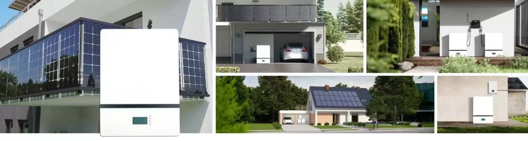
Advantages of the Wall-Mounted Design for a 200Ah Solar Storage Battery: Reduced Installation Space

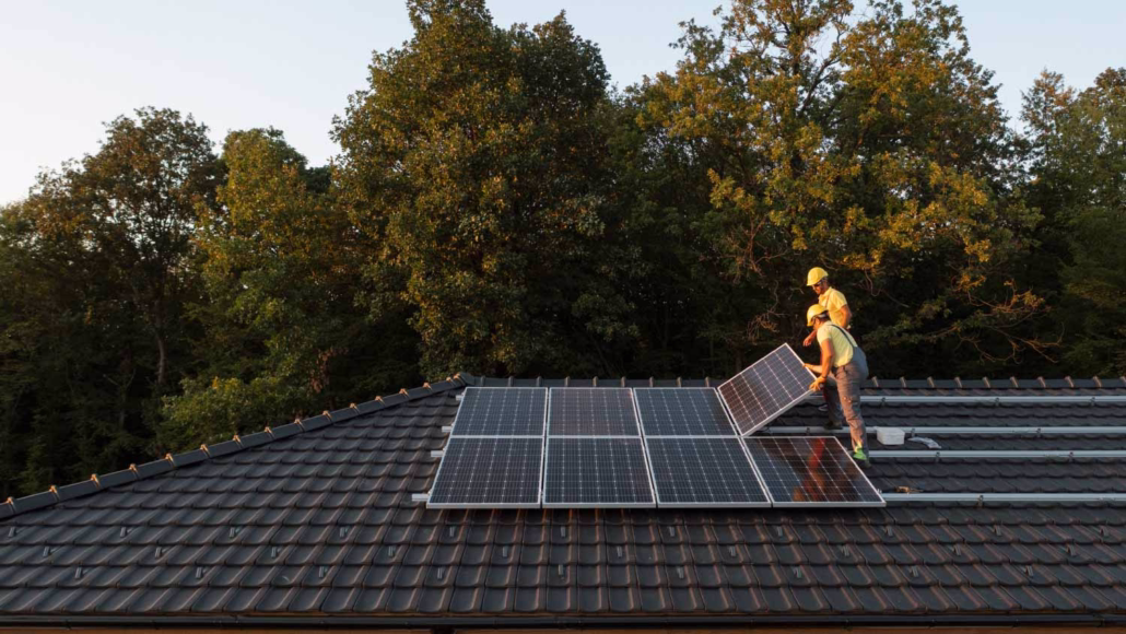
batteriesBeyond the performance requirements for a 200Ah solar storage battery, many homeowners face the additional challenge of installing a lithium-ion solar battery without encroaching on their storage rooms, laundry areas, garages, or utility areas. The wall-mounted 200Ah solar storage battery addresses this dilemma by lifting the unit off the floor—thereby reducing clutter and enabling a more efficient installation layout. In many smaller homes, this configuration can save up to 60% of floor space compared to traditional floor-standing battery cabinets, all while delivering the same essential energy storage capacity.

Why Does the Wall-Mounted Design Solve Space Challenges?

In smaller homes, unused wall space is often the most overlooked asset. Garage corners, utility room walls, or interior storage areas may sit idle for years—spaces that homeowners could otherwise use to house a reliable 200Ah solar storage battery. This is where the ingenuity of a wall-mounted energy storage system lies. Instead of requiring a large footprint for a floor-standing cabinet, it extends vertically, harnessing previously unused wall space. For homeowners with limited living space, this design transforms a spatial constraint into a distinct design advantage.

This is particularly crucial for compact homes, townhouses, apartments with dedicated utility closets, and smaller villas—settings where appliances, shelving, water heaters, or HVAC equipment may already occupy storage rooms or utility areas. Traditional floor-standing battery systems often conflict directly with these existing spatial demands. In contrast, wall-mounted lithium-ion solar batteries elevate the energy storage unit above floor level, thereby freeing up valuable floor space for daily activities, maintenance access, and safe passage during emergencies.

Why Does the Wall-Mounted Design Solve Space Challenges

How Wall-Mounted 200Ah Solar Storage Battery Saves Up to 60% of Floor Space

The most immediate benefit of a wall-mounted installation is the reduction in floor footprint. In many residential layouts, a floor-standing battery cabinet requires not only the space occupied by the cabinet itself but also additional clearance surrounding the unit to ensure adequate airflow, accessibility, and ease of maintenance. Once these necessary clearances are factored in, the actual total space required is often far greater than the cabinet’s dimensions alone would suggest. The wall-mounted 200Ah solar storage battery utilizes vertical mounting space, thereby significantly reducing its physical footprint. In smaller homes, this solution can save up to 60% of floor space compared to traditional floor-standing energy storage systems. The space saved can be repurposed for laundry appliances, storage shelving, or cleaning supplies. Furthermore, it minimizes the risk of accidental collisions with the battery system, thereby enhancing overall safety.

How Wall-Mounted 200Ah Solar Batteries Save Up to 60% of Floor Space

Enhancing Layout Efficiency and Residential Practicality

The primary reason homeowners choose wall-mounted energy storage battery is not merely their small footprint, but rather their ability to facilitate more efficient space utilization. When the battery is mounted on the wall, installers can arrange it more logically alongside inverters, distribution boxes, or solar control equipment. Cable routing also becomes shorter and neater, thereby simplifying the installation process.

For homeowners, this translates to a superior living experience. Rather than having to accommodate a large battery cabinet on the floor and navigate around it, a wall-mounted battery keeps the floor clear, facilitating ease of movement and storage. This is particularly practical for homes where the battery system is situated near laundry areas, workshops, or utility zones within entryways. In such scenarios, wall-mounted lithium-ion solar batteries effectively preserve the room’s functionality while providing reliable backup power and solar energy storage.

Lithium-Ion Solar Battery: Ideally Suited for Wall-Mounted Designs

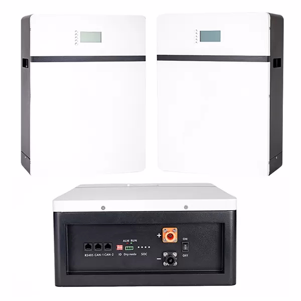
Lithium-ion solar batteries feature high energy density, stable discharge performance, and a long cycle life, making them the ideal choice for vertically mounted energy storage cabinets. A 200Ah solar storage battery utilizing lithium-ion cells can deliver substantial usable capacity while maintaining a moderate size and weight.

Furthermore, because the wall structure must safely support the load and the battery must remain stable over years of operation, manufacturers can also integrate lithium-ion solar batteries with intelligent battery management systems, making them well-suited for such applications. These systems allow for real-time monitoring of the battery’s cell balance, temperature, voltage, and current. When the inherent chemical properties of lithium-ion solar batteries combine with advanced BMS controls, they provide homeowners with an energy storage solution that is safer, more efficient, and more reliable than traditional battery technologies.

Lithium-Ion Solar Battery Ideally Suited for Wall-Mounted Designs

Thermal Management and Safety Advantages of 200Ah Solar Storage Battery

In any residential battery installation, thermal management is one of the most critical engineering considerations. Proper installation of a wall-mounted 200Ah solar storage battery can significantly enhance its thermal performance; by keeping the unit elevated, wall mounting prevents the accumulation of dust and ground-level debris, thereby ensuring unimpeded airflow. Furthermore, wall mounting typically facilitates maintaining an adequate ventilation zone around the battery enclosure. This promotes natural heat dissipation, allowing the battery to operate within a safer and more optimal temperature range.

In terms of safety, wall-mounted energy storage batteries typically feature fire-resistant enclosures, integrated protection circuitry, and robust mounting hardware—all designed to ensure the system operates stably and securely under normal conditions. When installed correctly, the battery remains firmly anchored, easily accessible for maintenance, and safely positioned to prevent accidental contact.

An Ideal Installation Method for Small-Scale Residential Energy Storage

For homeowners seeking a reliable solar energy storage system without sacrificing valuable floor space, the wall-mounted 200Ah solar battery offers a highly practical solution. By combining the space-saving benefits of vertical mounting with the inherent advantages of lithium-ion solar battery technology, it integrates seamlessly into smaller residential environments. Capable of saving up to 60% of floor space while enhancing installation flexibility and supporting safe, long-term operation, this solution provides homeowners with a more convenient and efficient approach to energy storage installation.

How does a hybrid solar power system balance solar, battery, and Grid Power for a stable supply?

A hybrid solar power system does more than generate electricity; it continuously determines how to allocate and store every watt produced, as well as when to draw backup power from the utility grid. It is precisely this integrated design that makes hybrid solar systems ideally suited for homes, businesses, farms, and remote locations where power interruptions cannot be tolerated. When sunlight is abundant, the system utilizes solar energy directly. When electricity demand rises—or when cloud cover reduces power generation—the system seamlessly switches to battery storage. Should neither solar power nor battery storage be sufficient to meet demand, the system draws power from the utility grid without interrupting critical loads. In other words, a robust hybrid solar solution dynamically balances these three energy sources in real time, thereby providing users with a stable, uninterrupted power supply.

How Hybrid Solar Power Systems Determine Power Flow?

At the core of every hybrid solar system lies a solar output that exceeds load demand; the surplus energy is used for consumption, energy storage, and grid conditions. Rather than simply “turning on” the solar array or “turning off” the grid, the system continuously reads the current solar output, the home or facility’s electrical load, battery charge levels, and grid availability. Based on these inputs, the hybrid solar system identifies the most efficient energy pathway. If solar energy is sufficient to meet the load demand, the system will prioritize solar power, as direct consumption avoids energy losses associated with conversion processes.

Should the solar output exceed the load demand, the surplus energy will be utilized to charge the batteries; furthermore, if conditions permit, this excess electricity may also be fed back into the public grid. Conversely, if the solar output proves insufficient, the batteries will step in to bridge the power supply gap. Should the battery charge level drop below a predetermined threshold, the utility grid automatically intervenes to provide power.

A hybrid inverter typically manages this operational logic in conjunction with an energy management system. Acting as the central controller, the inverter converts the DC generated by the PV array and batteries into AC suitable for powering electrical loads, while simultaneously coordinating battery charging and discharging. High-quality hybrid solar solutions leverage this controller to prevent energy waste, protect the batteries from overcharging or deep discharge, and maintain a stable power output even amidst rapidly changing weather conditions.

How Hybrid Solar Power Systems Determine Power Flow

Solar-Priority Operation and Self-Consumption in a Hybrid Solar Power System

Most hybrid solar systems employ a “solar-priority” strategy, as solar energy is the most cost-effective power source once the system is installed. In a solar-priority hybrid solar system, the PV array immediately supplies power to the building’s loads. This reduces reliance on the utility grid and boosts self-consumption—the proportion of generated solar energy consumed on-site rather than exported or lost. If the load is lower than the generation output, the system stores the surplus electricity in batteries. If the batteries reach full capacity and regulations permit power export, the system can feed the excess electricity back into the grid.

This approach enhances efficiency in two ways. First, it minimizes conversion steps; energy delivered directly from the solar array to the loads avoids the additional losses associated with storage and subsequent discharge. Second, it prioritizes renewable energy, thereby reducing operating costs and carbon emissions.

Solar-Priority Operation and Self-Consumption in a Hybrid Solar Power System

Battery Scheduling in Hybrid Solar Power Systems

Batteries are the key component that transforms a solar installation from a mere daytime power generator into a stable, reliable power solution. In a hybrid solar system, batteries store surplus energy generated during the day and release it when solar generation declines. This enables the system to handle cloudy days, evening peak demand periods, and even brief power outages without the user noticing any interruption. Properly managed batteries also contribute to grid stability. By avoiding excessive power exports during midday and excessive imports during the night, the system smooths the load profile, making energy usage more predictable.

Factors such as state of charge, temperature, and battery chemistry govern battery scheduling. For instance, Lithium Iron Phosphate (LiFePO4) batteries handle frequent charge-discharge cycles well and typically integrate effectively with residential and commercial hybrid inverters. The control system maintains battery voltage and temperature within safe operating ranges while determining when to charge, discharge, and reserve backup capacity. Many hybrid solar solutions also reserve a minimum battery capacity specifically for emergencies. This reserved capacity ensures that critical loads remain powered during a utility grid outage. Thus, the battery serves as more than just an energy storage device; it acts as a vital stabilizer for the entire system.

Grid Interaction and Backup Support

The utility grid constitutes the third pillar of a hybrid solar power system. Rather than replacing solar generation or battery storage, the grid serves as both a safety net and an economic tool. When solar generation and battery storage are sufficient, the system can reduce—or even eliminate—the need to purchase electricity from the grid. When weather conditions are adverse, electricity demand rises, or battery storage is insufficient, the power grid automatically steps in to supplement the power supply. It is precisely this backup power capability that gives hybrid systems a distinct reliability advantage over standalone solar-plus-storage systems.

Furthermore, with Time-of-Use (TOU) pricing, this system charges the battery during off-peak hours—when electricity rates are lower—and discharges it during peak demand periods—when rates are higher. Additionally, in regions where Net Metering is permitted, the system can export surplus solar power back to the grid. In the event of a power outage, the inverter isolates the building from the grid, relying solely on solar generation and battery storage to maintain a continuous power supply to critical loads. A robust hybrid solar solution manages these transitions seamlessly—without causing light flickering, device restarts, or unsafe back-feeding into the grid. This requires sophisticated rapid-switching logic, anti-islanding protection, and precise synchronization with local grid regulations. The ultimate result is a stable, uninterrupted power supply that combines the energy-saving benefits of renewable sources with the reliability of utility-grade backup power.

How Do Hybrid Solar Solutions Ensure Stable, Long-Term Power Supply?

The optimal approach to deploying a hybrid solar system involves sizing its components based on actual electricity consumption rather than merely on estimated capacity. The first step is to measure or estimate daily kWh consumption and peak power demand. The second step involves analyzing local solar resources—specifically focusing on the months with the poorest sunlight conditions, rather than relying solely on annual averages.

This is a critical consideration, as the system must remain fully operational even during overcast periods when solar generation output drops significantly. If the solar array is undersized, the grid or the battery bank will have to shoulder an excessive portion of the load. If the battery bank is undersized, the system will be unable to meet peak evening demand or sustain power during outages. Conversely, if the inverter is undersized, it may fail to function properly when motor-driven appliances or compressors—which draw high surge currents—start up.

A high-performance hybrid solar solution achieves this balance across its various components. The PV array should be sized to meet daytime electricity demand while simultaneously recharging the batteries within a reasonable timeframe. The battery bank should store sufficient usable energy to cover nighttime consumption and any anticipated periods of overcast weather. Finally, the inverter must be capable of meeting both continuous electricity demand and the momentary peak power surges required by appliances and motors. In practical terms, this means that residential homes, small commercial facilities, and remote microgrids each require distinct design strategies tailored to their specific needs.

How Do Hybrid Solar Solutions Ensure Stable, Long-Term Power Supply

Protection, Monitoring, and Maintenance: Ensuring Supply Stability

Even the most expertly designed hybrid solar power systems require protection and maintenance to ensure stable, long-term operation. Inverters must be capable of safeguarding against overvoltage, undervoltage, overload, short circuits, reverse polarity, and thermal stress. Battery Management Systems must protect batteries from unsafe charging conditions and deep discharge. Grid interfaces must prevent back-feeding into the grid during power outages and comply with local electrical standards. These safety measures are not optional; they are the critical elements that enable a hybrid system to operate safely under both routine and emergency conditions.

Monitoring is equally vital; modern hybrid solar systems should track solar output, battery charge levels, grid input/output, and fault events in real time. This data empowers users to detect performance anomalies early, enabling proactive intervention before minor issues escalate into major problems. For instance, a gradual decline in battery capacity, recurring inverter temperature alerts, or a sudden drop in PV output could all signal potential underlying issues. Routine cleaning, connector inspections, firmware updates, and battery health checks ensure that the system consistently operates at its designed performance level.

Achieving a Reliable Energy Balance

A hybrid solar power system offers far more than mere energy generation; it provides a dynamic, intelligent energy management solution that ensures stable operation in an ever-changing environment. By seamlessly coordinating solar generation, battery storage, and grid interactions, a hybrid system optimizes energy flow in real time—prioritizing renewable energy while providing reliable backup power whenever needed. This balanced approach not only enhances energy efficiency but also significantly reduces reliance on the utility grid, thereby lowering long-term electricity costs.

Modular off grid solar system vs Traditional Off Grid Systems: Scalability & Cost Comparison

A single 3kW inverter and a battery bank evolve into a 30kW microgrid five years later, powering multiple buildings—all without the need to dismantle the original equipment. This seamless scalability precisely highlights the advantage of a modular off grid solar system: users can stack small modules to expand capacity, increase redundancy, and mitigate the risk of over-investment. In contrast, engineers typically pre-design traditional off-grid systems for a specific capacity, which requires organizations to make a substantial upfront investment; as demand grows, they often must replace the systems prematurely or undertake costly retrofits. Consequently, we will analyze component architecture, deployment protocols, BOS differences, lifecycle costs, and practical expansion mechanisms. Additionally, I will quantify typical cost drivers and provide best practices for procurement and commissioning, offering you a clear, intuitive understanding of the distinctions between these two types of off-grid solar systems.

Architecture of Modular Off Grid Solar System: Interoperability and “Plug-and-Play” Expansion

Modular off grid solar systems consist of reusable modules that can operate independently or in concert. Typical modules include: standardized strings of PV panels, stackable 48V or 51.2V battery banks, inverter/charger modules capable of parallel operation, and a communication backbone. Engineers meticulously design each module to be electrically and mechanically interoperable, allowing them to add new modules with minimal reconfiguration.

Key Technical Advantages:

Phased Expansion: As demand grows, additional battery modules or PV strings can be added. This avoids upfront over-construction and mitigates financial risk.

Redundancy and Fault Tolerance: A parallel inverter architecture enables the system to withstand the failure of a single unit; replacing a faulty module is faster and causes less disruption than replacing a monolithic battery bank.

Standardized Commissioning: Repeatable commissioning procedures simplify training and reduce commissioning time, particularly across multiple sites.

From an electrical design perspective, modular systems rely on a clear bus architecture and communication protocols. For instance, vendors may employ a 48V DC battery bus and utilize an enslaver/agent configuration for inverter synchronization. Power distribution is coordinated via inverter firmware and BMS messaging. This design minimizes “single-point” upgrade efforts: to double available capacity, one needs to add matching battery modules and update the EMS settings, without dismantling and replacing the entire power system.

Architecture of Modular Off Grid Solar System

Traditional Off Grid System: Monolithic Design, BOS Impact, and Upgrade Pain Points

Engineers typically design traditional off-grid systems based on the projected peak load and the required days of autonomous operation at the time of installation. Designers select an inverter rated for the peak load, a battery bank sized in Ah relative to the system voltage, and a PV array capable of recharging the battery bank within an acceptable timeframe. While this “right-sizing” approach is highly efficient initially, it presents several drawbacks:

Substantial Upfront Capital Expenditure: Traditional systems require organizations to invest the entire budget upfront—covering batteries, inverters, PV generation, and civil works—which creates a significant barrier for many smaller organizations.

Upgrade Complexity: Increasing capacity later typically necessitates replacing the inverter with a higher-rated unit, fabricating new busbars, and undertaking extensive rewiring. Such upgrades can be costly and prone to causing system downtime.

Limited Operational Flexibility: If load requirements change, a monolithic system may reach its capacity limits or require support from a backup generator.

The impact of Balance of System components is significant. Large, fixed systems require thicker cables, larger combiner boxes, and larger battery rooms—all of which exponentially increase costs and installation complexity. For remote deployments, transporting a single large battery bank can be logistically more challenging than transporting multiple smaller modules.

Traditional Off Grid System

Cost Comparison of the Two Approaches

At first glance, modular components have a higher unit cost per capacity. A stackable 5 kWh Lithium Iron Phosphate battery module—including its enclosure and BMS—typically carries a higher per-kilowatt-hour cost than a mass-produced, custom-built battery bank. However, to gain a true understanding of the situation, one must consider it from a lifecycle perspective.

Modular Capital Expenditure Model: Organizations start with a smaller initial acquisition scale and pay costs on demand, aligning their investment with business growth. This lowers the barrier to entry and synchronizes expenditure with cash flow. For instance, a medical clinic might initially acquire 10 kWh of usable capacity and then gradually add more modules over three years, as budget permits.

Traditional Capital Expenditure Model: Characterized by high initial investment, though the hardware cost per kilowatt-hour is slightly lower, and the number of interconnection components is fewer.

Crucially, modular systems can minimize wasted capacity. If demand is expected to grow slowly, building a massive battery system right from the start means capital will sit idle for years. Conversely, phased procurement better aligns with actual consumption patterns and yields a higher short-term ROI. NPV models from many vendors demonstrate that, when accounting for financing costs and operational flexibility, modular systems can result in lower total financing costs over 10 years.

Differences in BOS and Installation Costs

Differences in BOS costs are most evident in on-site expenses. Traditional off grid solar systems typically utilize fewer but larger-gauge cables, centralized junction boxes, and require substantial civil engineering work—such as constructing dedicated battery rooms and installing cable trays. While the installation work is physically demanding, it is relatively concentrated in time.

Modular off grid solar system shift labor away from heavy civil engineering tasks toward repetitive, smaller-scale installation work—specifically, mounting modules, inserting standardized connectors, and securing lugs to busbars. Although the total number of connectors increases, each connector is smaller and simpler. Since there is no need for specialized heavy lifting equipment or large construction crews, labor costs become more predictable—and, in remote locations, typically lower. Furthermore, while a traditional 100 kWh system might require a full day of heavy lifting and the presence of one or two electricians, a modular approach—combining ten 10 kWh modules—allows the same crew to complete the installation in multiple smaller visits, thereby simplifying logistics and avoiding costly on-site mobilization fees.

Off grid solar system installation

Optimal Use Cases for Each Off-Grid Solar System Type

Choose a modular off-grid solar system under the following circumstances:

  • Stakeholders expect demand to grow or fluctuate unpredictably—for instance, during community electrification projects or when organizations scale up pilot projects to full-scale deployment.
  • Budget constraints necessitate a phased investment strategy.
  • Redundancy, backup capabilities, and maintaining uptime in the event of partial system failure are top priorities.

Choose a traditional off-grid system under the following circumstances:

  • The load profile is known, stable, and unlikely to change significantly.
  • The site offers easy access, making a single, large-scale installation event a cost-effective option. Reducing hardware costs per kilowatt-hour is a top priority—one that is well-funded.
  • Operators tend to enter into comprehensive maintenance contracts under which a single party assumes full responsibility.

More Flexible, Reliable, and Scalable Energy Solutions

While traditional off grid solar systems remain effective for projects with stable and predictable energy demands, they typically require substantial upfront investment and offer limited flexibility when energy requirements fluctuate. In contrast, modular off grid solar system introduce a more adaptable architecture, enabling users to incrementally expand system capacity, optimize capital expenditure, and mitigate operational risks over time. By leveraging standardized components, scalable battery storage, and parallel inverter configurations, modular systems allow energy infrastructure to scale in alignment with actual demand growth.

Monocrystalline solar panel: High-Purity Silicon Material Delivers 24% Lab Peak Efficiency

Among the various photovoltaic technologies available today, monocrystalline solar panel is distinguished by their high efficiency and widespread applicability. Thanks to advancements in semiconductor engineering and manufacturing processes, the laboratory peak efficiency of monocrystalline solar panels has reached 24%. For customers selecting solar panels for applications such as solar streetlights, rooftop systems, or off-grid solar installations, efficiency is one of the most critical performance metrics. Higher efficiency means that, within the same physical footprint, a solar panel can convert a greater amount of sunlight into usable electrical energy. This advantage is particularly significant in applications where installation space is limited—such as solar streetlight systems, urban rooftops, and compact off-grid solar solutions.

High-Purity Silicon in Monocrystalline Solar Panel

The exceptional efficiency of monocrystalline solar panels stems from their fundamental material: high-purity monocrystalline silicon. Unlike polycrystalline silicon solar panels, which are composed of multiple silicon crystals, monocrystalline cells are fabricated from a single, continuous silicon crystal structure. This uniform lattice structure allows electrons to move more freely within the semiconductor material, thereby minimizing energy losses during the photovoltaic conversion process.

Manufacturers typically use the Czochralski crystal growth process to produce monocrystalline silicon, slowly pulling a cylindrical silicon ingot from a molten silicon melt under controlled conditions. This process yields a highly ordered crystal structure with minimal grain boundaries, thereby enhancing electrical conductivity and overall energy conversion efficiency. In high-end photovoltaic manufacturing, high-purity silicon feedstock is utilized to minimize impurities and defects within the crystal lattice. Fewer defects translate to fewer recombination centers. Consequently, monocrystalline silicon solar panels can achieve higher open-circuit voltages and superior carrier mobility—two factors that are crucial for attaining efficiencies approaching or exceeding 24% under laboratory test conditions.

monocrystalline silicon

Solar Cell Architectures Achieving 24% Efficiency

Material purity alone is insufficient to achieve record-breaking efficiencies. Modern monocrystalline silicon solar panel also rely on advanced photovoltaic cell architectures designed to maximize light absorption while minimizing electrical energy losses.

Several cutting-edge technologies contribute to the enhancement of solar cell efficiency:

  • PERC technology boosts performance by incorporating a passivation layer on the rear surface of the solar cell. This passivation layer reflects unabsorbed sunlight into the silicon wafer, thereby increasing the probability that photons will generate an electric current.
  • TOPCon technology further enhances performance by introducing an ultra-thin oxide layer to reduce recombination losses at the contact interface. TOPCon cells have emerged as one of the most promising technologies for next-generation high-efficiency monocrystalline solar panels.
  • HJT technology combines crystalline silicon with thin layers of amorphous silicon to achieve superior surface passivation and enhanced voltage performance. HJT cells demonstrate remarkable potential for high efficiency while maintaining excellent temperature characteristics.

These innovations have significantly boosted the energy conversion efficiency of solar panels, enabling laboratory prototypes to reach approximately 24% efficiency, while commercial modules typically achieve 21% to 23% in real-world applications.

Solar Cell Architectures Achieving 24% Efficiency

Real-World Performance and Applications of Monocrystalline Solar Panel

While an efficiency of 24% represents peak performance under laboratory conditions, actual operating environments differ significantly from controlled testing settings. Factors such as temperature fluctuations, dust accumulation, shading, and seasonal variations in sunlight can all impact the actual power output of solar panels.

Nevertheless, monocrystalline solar panels retain distinct advantages in practical applications. Compared to other photovoltaic technologies, their higher efficiency allows them to generate more electricity per square meter. This makes them particularly valuable in installations with limited space—such as rooftop solar systems, solar-powered streetlights, and residential solar installations. Another key advantage of monocrystalline solar modules is their excellent temperature coefficient. While the efficiency of solar panels naturally declines as temperatures rise, advanced cell designs help mitigate this performance degradation. Consequently, monocrystalline panels can maintain higher power output in hot climates than many other solar technologies.

Real-World Performance and Applications of Monocrystalline Solar Panels

Durability, Lifespan, and Reliability

When investing in a solar system, long-term reliability is a critical consideration. Engineers design high-quality monocrystalline solar panels for reliability and ensure they operate stably for decades, making them a dependable choice for both residential and commercial applications. Most high-end manufacturers offer a 25-year performance warranty, ensuring that solar panels retain a substantial portion of their original power output for decades. The typical annual degradation rate for monocrystalline silicon solar panels is approximately 0.4% to 0.6% per year. This means that even after 25 years of use, these panels can still generate more than 80% to 85% of their original power output.

Furthermore, modern solar panels undergo extensive testing to ensure their durability under extreme environmental conditions. These tests evaluate their tolerance to high humidity, thermal cycling, mechanical loads, and potential PID. Panels that pass these tests demonstrate robust resilience against environmental stresses, thereby ensuring the long-term stability of the system.

Key Applications of Monocrystalline Solar Panels

Due to their exceptional efficiency and durability, monocrystalline solar panels are widely used across a broad spectrum of solar applications. One of the most common applications is in solar streetlights, which require compact, high-efficiency panels to generate sufficient electricity for nighttime illumination. High-efficiency monocrystalline panels enable solar streetlights to operate reliably, even in regions with limited sunlight. Additionally, installers extensively use them in residential rooftop solar installations, where maximizing energy yield within limited roof space is paramount. Their superior efficiency allows homeowners to generate more electricity without expanding the installation footprint. Moreover, installers frequently deploy monocrystalline solar panels in off-grid solar systems, remote telecommunication stations, and agricultural solar solutions. In these environments, reliability and stable energy output are critical for maintaining uninterrupted operations.

Unlocking Maximum Efficiency

Monocrystalline silicon solar panels combine high-purity silicon, advanced cell structures, and durable designs to deliver exceptional energy efficiency and long-term reliability. Laboratory tests indicate that the efficiency of monocrystalline panels can reach up to 24%, enabling them to perform outstandingly in both residential and commercial settings, ranging from rooftop solar systems to solar streetlights and off-grid solutions. Their compact design, superior temperature performance, and exceptionally long service life ensure that investors and users can achieve maximum energy output while simultaneously minimizing space requirements, maintenance expenses, and long-term costs.

Solar Power Street Light vs Traditional Grid Street Lights: Cost/Installation/Energy Savings Comparison


For decades, most cities have relied on traditional grid street lights. However, with rising energy costs, expanding urban infrastructure needs, and increasing pressure to reduce carbon emissions, many cities and project developers are rethinking how street light systems are powered. Solar power street light integrate photovoltaic panels, LED lights, smart controllers, and energy storage batteries into a self-sufficient lighting system. They generate and store electricity during the day and automatically provide lighting at night, without relying on the public grid. For municipalities, contractors, and infrastructure planners, the key question is no longer simply whether Solar power street light is effective, but how they compare to traditional grid-connected streetlights in terms of cost, installation complexity, and long-term energy savings.

Differences between Solar Power Street Light and Traditional Grid System

Solar power street lights integrate photovoltaic panels, batteries, LED lights, controllers, and sometimes communication equipment into a single or modular pole system. In contrast, traditional grid streetlights rely on centralized distribution networks, powering the lights through underground or overhead conductors and using utility-grade light controllers or centrally managed lighting control panels.

The key architectural difference lies in independence versus grid dependence. Solar power street lighs operate as local micro-energy systems—generating, storing, and consuming energy on-site—significantly altering the project lifecycle. For planners, the advantages include eliminating mainline excavation and trench repairs, reducing coordination with utility companies, and faster approval processes in many areas. Conversely, traditional grid systems rely on existing or expanded power infrastructure, have lower unit costs for the lights themselves, and generally simpler power-quality requirements due to stable AC power

Differences between Solar Streetlights and Traditional Grid Systems

from utilities.

Upfront Costs and Capital Allocation

Upfront capital expenditure is often the most significant difference when comparing Solar power street lights and traditional grid streetlights. A high-quality Solar street light, including photovoltaic modules, lithium batteries, LED lights, and a smart controller, typically costs more per pole than a traditional grid-connected LED system, especially when grid power is readily available and service is nearby.

However, capital expenditure is more complex. Traditional installations often incur substantial civil engineering and utility coordination costs. These non-equipment costs can exceed the cost of the light fixture hardware, particularly in areas with high excavation costs, such as city centers, historic districts, or hardscape. Solar power street lights, utilizing trenchless foundations and plug-and-play installation, avoid these civil engineering costs. The cost advantage of Solar power street lights is evident for projects where trenching or extending service lines is costly or impossible.

Operating Costs and Energy Savings of Solar Power Street Lights

Solar power street lights effectively shift energy costs from recurring operating expenses to one-time capital expenditures. Traditional grid LED street lights consume municipal electricity every night; over their 25-year lifespan, electricity bills accumulate. In contrast, Solar power street lights can generate and store their own energy, eliminating the need for lamp-based electricity bills and typically achieving decades of energy independence. This translates into substantial savings for municipalities paying retail or demand-based electricity rates.

The payback period for Solar power street lights differs significantly from that of grid-connected street lights. In situations with high grid costs or complex civil engineering conditions, the payback period is 2-8 years; in situations with low grid costs and low civil engineering costs, the payback period is longer. Furthermore, fleet-level modeling typically indicates that solar systems offer predictable operating expenses, which is attractive for municipal budgeting. Finally, changes on the demand side must be considered. For example, the relative economic advantage of solar energy will increase when utility fees rise, or future grid decarbonization reduces the marginal value of the grid.

Operating Costs and Energy Savings of Solar Power Street Lights

Installation Comparison of Solar Power Street Light and Traditional Grid Systems

One of the most significant practical advantages of Solar power street lights is their quick and easy installation. Integrated or modular solar poles simplify on-site work, from pole placement to mechanical assembly to a brief commissioning process. In many cases, installation can be completed in a day without extensive earthwork. Installation teams only need basic skills, not high-voltage grid interconnection. For suppliers, this simplifies logistics: smaller personnel, fewer permits, and faster pole turnaround times.

Complexity and Coordination Costs of Grid-Connected Installation

In contrast, installing traditional grid-connected street lights typically requires trenching, coordinating with utilities, and managing traffic. While the lights themselves are simple in structure, the civil engineering is complex: excavation, pipe laying, wire pulling, manhole installation, backfilling, pavement repair, and testing. Each step can cause delays: utility location, cross-departmental approvals, and inspections.

Also note that grid-connected installations typically require a licensed electrician and, in some cases, coordination with the power company for service extensions or load studies. For municipalities with limited staff, this often translates to high contracting costs and lengthy construction periods. In contrast, solar projects can be deployed quickly with just one qualified installer and a small civil engineering team. Overall, Solar power street lights offer significant advantages for projects that prioritize speed and minimize public disruption.

Choosing the Right Light for the Right Place

Solar power street lights and traditional grid street lights each have their place. Solar power street lights are particularly advantageous in areas where grid expansion costs are high, rapid deployment is crucial, and minimizing public disruption, achieving energy independence, and ensuring sustainability are paramount. Grid-connected streetlights are more suitable in areas with easy access to utilities, low energy costs, and ideal centralized management.

Off grid solar systems for farms: 3kW–30kW Sizing Guide for Smallholder & Large-Scale Farms

For many farmers, off grid solar systems are a tool for enhancing resilience and improving profitability. However, designing a suitable off-grid system requires rigorous capacity planning, not guesswork. We offer off-grid solar systems ranging from 3kW to 30kW for small and large farms. We will show you how to convert your farm’s actual load into a practical PV + storage system that safely and cost-effectively meets irrigation, cooling, lighting, and processing needs.

Size determination method for off grid solar systems for farms

The most common selection mistake is estimating PV system capacity based on roof area or the number of panels, rather than the load. For off grid solar system for farm, a detailed load list should be prepared first. List all equipment, their rated power, and actual daily operating hours. Categorize the load into three categories: critical, flexible, and optional.

Example load chart (based on a smallholder’s daily load):

  • Submersible irrigation pump: 2.2 kW motor × 2 hours = 4.4 kWh/day
  • Small cold storage: Average power 1.2 kW × 24 hours = 28.8 kWh/day
  • Lighting and others: 0.5 kW × 6 hours = 3 kWh/day
  • Control electronics and sensors: 0.2 kW × 24 hours = 4.8 kWh/day; Total approximately 41 kWh/day; Peak instantaneous demand ≈ 9–11 kW

Two key metrics stand out: daily electricity consumption and peak instantaneous power. Off grid solar system designs must meet both metrics simultaneously. Daily electricity consumption determines the configuration of photovoltaic power generation and energy storage systems; peak power determines the capacity of inverters and lines. Furthermore, the electricity cycle and time must be considered: while refrigeration is continuous, it is periodic. Use a smart meter with recorded data, or measure with a clamp meter over a typical week. To ensure the safety of the capacity configuration, always assume a conservative electricity-usage profile.

Size determination method for off grid solar systems for farms

Solar Resources and Worst Month Planning

Farm systems must be able to cope with seasonal low temperatures and cloudy days. To ensure the safety of off-grid system design, the capacity of the photovoltaic system and cells should be determined using the peak sunshine hours of the worst month, rather than the annual average. Local sunshine data can be obtained from NASA, Meteonorm, PVGIS, or the National Weather Service.

A rule of thumb for estimating photovoltaic system capacity: Required PV power (Wp) ≈ (Daily kWh demand) / (Worst month power collector value × System derating factor). Use a derating factor (0.7–0.8) to account for inverter losses, temperature losses, dust, and line losses. For example, with a daily demand of 20 kWh, a worst month power collector value of 3, and a derating factor of 0.75;

PV Wp ≈ 20,000 Wh / (3 × 0.75) ≈ 8,889 W ≈ 9 kWp.

Under ideal peak-sun conditions, this 9 kW peak-power photovoltaic array can generate the required energy, provided the battery capacity is sufficient to meet electricity demand during consecutive cloudy days. Do not plan the capacity of a photovoltaic power plant solely based on peak day projections.

Battery Capacity and Endurance: Planning for Power Outages and Cloudy Days

Battery capacity is key to improving system resilience. For off-grid solar systems on farms, a target number of autonomous operating days must be set.

Common Targets:

  • Short-term Resilience: 1 day of autonomous operation
  • Strong Farm Disaster Resilience: 2-3 days of autonomous operation
  • High Reliability/Off-grid Remote: 4-7 days of autonomous operation

Calculate Available Battery Capacity: Daily Electricity Consumption (kWh) × Endurance. Then consider the DoD and round-trip efficiency of the battery chemistry. For lithium iron phosphate batteries: available capacity is approximately 80-90%; for premium modules, assume 90% available capacity. Lead-acid battery systems require a higher nominal capacity to achieve the same usable energy due to their lower depth of discharge and shorter cycle life.

In addition, charge acceptance capability must be considered: large-capacity battery packs can withstand high currents; ensure the photovoltaic system and MPPT can meet the high charging-rate requirements; and be aware of BMS limitations. For water pumps and high-power motors, ensure the battery can provide the required inrush current (C-rate) and the inverter’s peak rating.

Inverter Capacity Selection for Off-Grid Solar Systems for Farms

For farm applications, motor inrush currents are high. When selecting an inverter, consider the following factors:

  • Continuous power rating ≥ the sum of your simultaneous continuous loads, with a 10-20% buffer margin.
  • Sufficient in surge rating to meet maximum motor starting requirements (e.g., a 3 kW water pump, 5 times the inrush current requires >15 kVA of surge power).
  • Provide pure sine-wave output for precision electronics and variable-speed drives.

For larger power installations such as 10–30 kW, multiple inverters can be connected in parallel or a hybrid inverter system can be used, supplemented by generator support, to distribute surge stress and increase redundancy. Microgrid inverters capable of independent operation and forming a voltage/frequency reference are particularly important when farms rely entirely on on-site power generation.

Furthermore, the system voltage must be determined: a nominal voltage of 48V is typically used for 3–10kW farms; for larger loads, a 120V/240V split-phase system or a 400V three-phase system is required. Higher DC bus voltages can reduce current and cable size in 20–30kW systems, but require suitable battery architecture and specialized technology.

Inverter Capacity Selection for Off-Grid Solar Systems in Farms

3 kW–30 kW configurations suitable for small to large farms

Small Farmers: 3 kW to 10 kW Off-Grid Solar Systems – Practical Solutions

Use Cases: Small farms, pumping water for several hours, LED lighting, small refrigerators or refrigeration, and basic processing.

Example Scenario A (3 kW System):

  • Daily Power Consumption: 6-8 kWh/day (Lighting, 1 kW/hour small water pump, refrigerator operation)
  • PV Power Generation: 3.5 kWp (approximately 10-12 panels, 300-360 Wp each), calculated based on a worst-month PSH of 2-3, with a derating of 0.75
  • Battery: 5-8 kWh usable capacity (e.g., 48 V, 100 Ah LFP battery pack), providing 1 day of continuous operation
  • Inverter: 3-4 kW pure sine wave, surge power 6-8 kW
  • Control Functions: MPPT charge controller, basic remote monitoring (cellular/LoRa), automatic pump start schedule

Practical Tips: Use high-efficiency monocrystalline silicon solar panels to reduce array footprint; add soft starters to the water pumps to reduce inverter surge requirements; schedule irrigation during periods of abundant solar energy to reduce battery cycle count.

Example Scenario B (7–10 kW Small Commercial):

  • Daily Load: 25–35 kWh (larger cold storage, milking machine running 2–3 hours, lighting)
  • PV: 8–12 kWp array
  • Batteries: Nominal capacity 20–30 kWh, runtime 1–2 days
  • Inverter: 8–10 kW hybrid inverter with 20–30 kVA surge capacity or parallel inverters
  • Add automatic generator start-up capability to cope with prolonged periods of insufficient sunlight.

Smallholders can benefit from a modular system that scales capacity as income or grant funding increases.

3 kW to 10 kW Off-Grid Solar Systems

Large Farms: 10 kW–30 kW Off-Grid Solar System

Use Cases: Large dairy farms, large irrigation systems, processing and cold chain, multi-building applications.

Example of a large farm (20 kW system):

  • Daily base load: 150 kWh/day (large cold storage, multiple pumps, processing)
  • PV power generation: 50–70 kWp, capacity determined based on pumped storage and derating factors during the worst month.
  • Batteries: Nominal capacity 100–200 kWh, range 1–2 days
  • Inverter architecture: Commercial hybrid inverters or stacked three-phase inverters providing 20–60 kW continuous power with coordinated control and generator synchronization.
  • Power distribution: Three-phase AC distribution with N+1 redundancy.

Key design considerations for large farms:

  • Use three-phase inverters or multiple inverters with a main energy management controller.
  • Consider ground-mounted arrays or trackers: Trackers can increase daily output and reduce variations in PV area during peak irrigation seasons.
  • Consider integrating diesel or biogas generators with automatic start-stop functionality to cope with long rainy seasons; use generators only as a last resort to reduce fuel costs.
  • During sustained periods of low photovoltaic power generation, implement sub-metering by load type to enable targeted demand control and smarter load shedding.
  • Large farms should treat the system as a microgrid, integrating SCADA, telemetry, demand-response logic, and planned maintenance windows.

10 kW–30 kW Off-Grid Solar System

Designing Robust Off Grid Solar Systems for Farms

Designing off-grid solar systems for farms requires quantifying actual loads, planning for the worst months of solar availability, determining battery capacity based on the required resilience level, and selecting an inverter architecture that matches peak power and surge demand. Small farms (3-10 kW) can typically use modular LFP batteries and a single hybrid inverter with appropriate load dispatch; large farms (10-30 kW and above) require a microgrid sensing and control system, three-phase power, and a combination of photovoltaic, energy storage, and backup generators. Of course, the first consideration should be energy-saving measures, using high-efficiency monocrystalline silicon solar panels where rooftop or land space is limited, and prioritizing modular, scalable battery systems so that investment can increase as demand grows.

Do TÜV-certified off-grid solar systems meet international safety standards?

In remote areas, off-grid solar systems ensure that villages remain brightly lit at night, with rooftop solar panels and battery banks illuminating the entire community, and schools can operate without generators. This outcome depends not only on the solar panels and inverters, but also on engineers rigorously controlling the system design, assembly, and testing processes to prevent electric shock, fire, or premature failure. TÜV-certified off-grid solar systems provide this confidence through independent, repeatable testing and safety verification of components and the entire system.

The Meaning of TÜV Certification and Its Correspondence with International Standards

TÜV Certification is not a single testing program, but a group of globally recognized independent testing and certification service organizations. When you see the phrase “TÜV-certified off-grid solar system,” it usually means that a TÜV certification body has tested the entire off-grid solar system or its key components to confirm that they meet specific standards. There are two common certification methods: component certification (e.g., solar modules conforming to IEC 61215/61730, inverters conforming to IEC 62109, and batteries conforming to relevant standards), and system-level certification.

For example, TÜV solar kit certification verifies whether the supplied components can be safely integrated and whether the installation and documentation comply with relevant specifications. System certification typically covers electrical safety, mechanical integrity, protection rating, and completeness of documentation. Therefore, in practice, a TÜV-certified off-grid solar system indicates that a qualified testing laboratory has verified the components’ compliance and the system’s integrated safety performance, rather than just a marketing claim of “high quality.”

TÜV Certification

Technical Standards Coverage: Electrical, Mechanical, Environmental, and Functional Safety

Electrical safety is paramount. TÜV audits typically assess whether off-grid solar inverters and their associated photovoltaic combiner boxes, DC circuit breakers, and AC converters comply with standards such as IEC 62109 and IEC 60364, as well as locally recognized equivalent standards. For battery storage, third-party laboratories typically conduct tests such as IEC 62619 or UL 1973 certification and perform functional safety testing on the battery management system. TÜV’s inspection includes insulation resistance, coordination of DC and AC overcurrent protection, anti-islanding/switching logic for hybrid systems, and photovoltaic reverse polarity and DC arc protection.

Since off-grid systems may include photovoltaics, inverters, batteries, and backup generators, TÜV assesses the control logic to prevent unsafe reverse feeding and ensure orderly switching—a critical safety feature in remote installations. Therefore, as long as the certificate references specific test standards and the certificate’s scope matches the deployed configuration, TÜV-certified off-grid solar systems generally meet the electrical protection requirements set by international safety standards.

TÜV-certified off-grid solar systems guarantee durability

Off-grid solar systems are exposed to harsh conditions year-round, including wind, snow, dust, moisture, and extreme temperatures. TÜV certification typically includes mechanical performance assessments, such as structural calculations for pole, bracket, and component installations; wind and snow load testing; and vibration or shock testing for mobile systems. Environmental testing examines the UV resistance of polymer components, salt spray testing for coastal deployments, and the enclosure’s IP protection rating (IP54, IP65, etc.).

If a product is marked as a TÜV-certified off-grid solar system, the manufacturer must provide evidence demonstrating that the mounting hardware and enclosure can withstand local environmental conditions and that the connectors and enclosure remain safe under such conditions. This requirement is particularly important for off-grid solar systems deployed in harsh climatic environments, because seal failure or fastener corrosion can quickly lead to electrical failures. TÜV’s mechanical performance and IP protection rating tests are fully compliant with international standards, including IEC 60529 (IP protection rating) and ISO structural testing specifications.

TÜV-certified off-grid solar systems guarantee durability

System Integration and Component Interoperability of TÜV-Certified Off-Grid Solar Systems

Component certification is necessary, but not sufficient. TÜV-certified off-grid solar systems emphasize integration: the interaction between photovoltaic modules, inverters, BESS, BMS, and mechanical systems. Integration testing simulates faults and confirms that the system’s protection layers can respond safely—for example, the BMS signals to stop inverter charging before overvoltage occurs, and contactor disconnection does not cause voltage spikes.

In addition, TÜV may test communication interoperability (CAN, Modbus) and the effectiveness of isolation measures. Purchasers should request a certified test plan and focus on explicit system-level testing rather than on component declarations alone. TÜV-certified off-grid solar systems with proven BMS/inverter communication scenarios reduce operational risks compared to kits loosely assembled from certified components.

Compliant with IEC, ISO, UL, NEC, and National Regulations

TÜV testing and certification bodies typically test in accordance with internationally recognized standards (e.g., IEC, ISO). They may also conduct tests compliant with national standards, such as North American UL standards or Japanese JIS standards. TÜV certificates usually list the standards referenced. For example, a TÜV-certified off-grid solar system for multiple markets may comply with IEC 61215/61730, IEC 62109, IEC 62619, and relevant grid-connected standards.

For systems installed in the United States, buyers should ensure that system components have UL certification or a TÜV certificate explicitly demonstrating compliance with UL requirements. TÜV certification can often expedite regulatory approval processes because the competent authority (AHJ) recognizes independent third-party test reports. Nevertheless, installers will still need local permits and may need to provide test reports or witness the commissioning process. TÜV certification can reduce friction in the approval process, but cannot replace local regulatory compliance requirements.

Compliant with IEC, ISO, UL, NEC, and National Regulations

TÜV Certification is the Foundation for Compliance with International Safety Standards

TÜV-certified off-grid solar systems meet or exceed international safety standards in many cases because the certification process tests all aspects, including electrical, mechanical, environmental, and functional safety, as a whole. However, certification is only one part of a safe deployment: system-level integration testing, clear commissioning and maintenance documentation, firmware management, and matching the certified configuration to your site conditions are equally important. By using TÜV-certification system kits, verifying the scope of certification, and following the supplier’s commissioning and lifecycle management processes, project owners can be confident that their off-grid solar systems will operate safely and reliably under both typical and adverse conditions.

Off grid solar inverter: Multiple Protection Features Eliminate Short Circuit/Overvoltage Risks

When a remote off grid cabin relies on solar power and a battery bank, a single wiring error or voltage spike can derail your energy plans. That’s why choosing an off grid solar inverter with comprehensive protection is crucial. PowerDream’s off-grid solar inverters feature a multi-layered safety architecture, including PV reverse polarity protection, battery overvoltage protection, overload and short-circuit protection, temperature management, surge suppression, and integration with a battery management system (BMS) to prevent minor malfunctions from escalating into catastrophic consequences.

Essential Protection Features for Off Grid Solar Inverter

The first and foremost requirement is PV reverse polarity protection. One of the most common mistakes in rooftop or ground-mounted installations is reversing the PV connector: a reversed connector can damage diodes, stress the MPPT circuitry, and cause dangerous arcing. Therefore, professional off grid solar inverters are equipped with explicit PV reverse-polarity protection, which detects DC polarity at the input and prevents current flow until the polarity is corrected. PowerDream’s off-grid solar storage inverters employ dual hardware and firmware protections: the hardware blocks DC power in the event of reverse polarity, while the inverter’s control logic reports the fault to the monitoring interface and locks the device in a safe state. Furthermore, a DC surge protector at the photovoltaic input prevents damage to the inverter from high-voltage transients such as lightning strikes or grid switching.

Essential Protection Features for Off Grid Solar Inverter

Battery Overvoltage and Undervoltage Protection Functions in Off Grid Solar Inverter

In off grid solar systems, the battery is the core of the entire device and the most sensitive component to inverter performance. An excellent off grid solar inverter must have robust battery overvoltage protection and undervoltage cutoff. If the battery is modular or a large-capacity pack, it must be integrated with an external BMS.

PowerDream’s off grid solar inverters support configurable charging cutoff voltage, absorption/float charging voltage, and SOC-based charging limits. In addition, the inverter includes a hardware relay and a fast electronic circuit breaker that trips when the battery voltage exceeds a safe threshold or when the BMS issues a critical fault signal. For lithium batteries, the inverter firmware supports temperature-compensated charging setpoints and charging current limits to prevent battery overvoltage. On the other hand, undervoltage protection prevents the inverter from operating below a safe battery voltage, thus protecting the battery from damage and extending cycle life.

Short Circuit Protection and Overload Handling Functions

Short circuits and overloads can occur in off grid systems: pump blockage, incorrect load wiring, lightning strikes, or cable faults can all cause the inverter to withstand extremely high currents. A reliable off-grid solar inverter must quickly detect short circuits and disconnect the affected output to limit fault current and prevent downstream damage. PowerDream employs multi-stage current protection: the inverter power stage is equipped with fast electronic overcurrent detection, clearing high current transients within microseconds; simultaneously, electromechanical relays or contactors trip when a fault persists. The overload protection function is adjustable and supports phased response. More importantly, the inverter logs fault events and reports fault details to a remote monitoring system, allowing technicians to diagnose the root cause without costly on-site service.

Short-circuit protection and overload handling functions for off-grid solar inverters

Advanced Protection, Environmental Protection, and System Integration for Off Grid Solar Inverter

Thermal stress is a major cause of inverter failure. Off grid inverters typically operate in harsh, un-air-conditioned environments. Therefore, professional off grid solar inverters require active thermal monitoring, conservative thermal derating profiles, and a clear enclosure design to prevent thermal runaway. PowerDream’s BHYP off-grid solar inverter provides multi-sensor temperature monitoring and implements tiered thermal protection: it slowly drains when output power exceeds a set threshold; at extreme temperatures, it reduces the MPPT’s sensitivity to limit internal heat dissipation; and it forces a shutdown if the temperature exceeds safe operating limits. Additionally, for prolonged high-temperature operation, the inverter can notify the operator and record temperature trends to support preventive maintenance.

Surge Protection and Transient Voltage Suppression

Lightning strikes and grid switching can generate transient overvoltages that can propagate into off grid systems via photovoltaic arrays, AC reverse power supplies, and even grounding systems. A robust off-grid design considers surge protection a critical feature. PowerDream integrates surge protection devices (SPDs) on both the PV DC side and the AC output/standby input side of the inverter. These SPDs are coordinated: a type 1/2 equivalent surge protector on the AC input side and a high-energy DC surge protector on the PV input side. Additionally, the inverter includes internal clamping circuitry and MOVs to absorb residual energy. Importantly, you can maintain and replace the SPD very conveniently; multiple surge events degrade its performance, so you must replace it to maintain its effectiveness.

Surge Protection and Transient Voltage Suppression in Off-Grid Solar Inverters

Choosing a Protection-First Off Grid Solar Inverter

Choosing an off grid solar inverter is not simply about selecting the kilowatt rating; it’s more about choosing a protection-first architecture to prevent wiring errors, battery damage, overheating failures, and sudden transient events. PowerDream’s off-grid solar storage inverters integrate hardware and firmware protection features, including photovoltaic reverse-polarity protection, battery over- and under-voltage handling, short-circuit and overload trip coordination, temperature protection, and surge protection. These features work together to ensure the safe and efficient operation of off-grid systems.

How can we solve the problem of the tedious and complicated installation of solar power street lights?

In many municipal and commercial projects, installing traditional grid-connected solar power street lights quickly becomes a civil engineering project, rather than a simple lighting upgrade. Traditional streetlights require trenching, laying underground cables, obtaining grid connection permits, coordinating transformers, and working with multiple subcontractors. The main challenges typically include underground cable laying, long-distance voltage-drop calculations, interference risks, and compliance checks for the power infrastructure. Trenching alone can account for 30% to 50% of the total project cost. Truly modern, simple, fast, and efficient solar streetlights should operate independently, without relying on centralized infrastructure.

The Independent Architecture of PowerDream Solar Power Street lights

Unlike traditional lighting networks, each PowerDream solar power street light is designed as an independent architecture. Each unit integrates high-efficiency solar panels, a smart MPPT controller, lithium batteries, and LED lights into a single monolithic or modular structure. Because each solar streetlight operates independently, there is no need for grid connection or underground cabling. This architecture fundamentally changes the installation process. Engineers no longer need to design centralized electrical layouts; they only need to determine the pole spacing and lighting requirements. Each solar street light can independently generate, store, and consume electricity. Therefore, there is no need for voltage balancing, transformer selection, or grid synchronization. This decentralized structure improves reliability, especially in remote infrastructure projects such as highways, industrial parks, and areas with limited maintenance access.

The Independent Architecture of PowerDream Solar Power Street lights

PowerDream Solar Power Street Lights: Trenchless Installation and Cost Optimization

Installing PowerDream solar power street lights requires only three main steps: erecting the poles, installing the solar street light fixtures, and securing the structure. No excavation, piping, or electrical cabinets are required. Because there is no need to lay underground cables, installers avoid common risks such as cable damage, water ingress, interference, or utility conflicts. This simplified installation method reduces reliance on manual labor and minimizes the use of heavy machinery. In many projects, installation time can be reduced by up to 60% compared to traditional street light systems.

Furthermore, trenchless construction significantly reduces indirect costs. No traffic diversion planning is needed in urban environments, and no environmental remediation work is required in landscaped areas. For rural and developing areas where grid expansion may be impractical or prohibitively costly, this self-contained solar street light solution is not only efficient but also crucial.

Trenchless Installation and Cost Optimization

All-in-One vs. Split-Type Solar Power Street Lights

PowerDream offers both All-in-One and split-type solar power street light configurations to meet diverse project needs. All-in-One solar power street lights combine all components—solar panels, batteries, controllers, and LED luminaires—into a compact unit, mounted directly on the pole. This design maximizes ease of installation and is ideal for rapid deployment in residential streets, sidewalks, and small commercial areas.

Split-type solar power street lights separate the solar panels and battery modules, allowing each to operate independently. This configuration offers greater flexibility in optimizing tilt angles, battery capacity, and lighting output. It is particularly advantageous for highways, ports, and industrial parks requiring higher lumen output and longer runtime. Both designs adhere to the trenchless installation concept, providing a scalable solution without sacrificing structural integrity or performance reliability.

All-in-One vs. Split-Type Solar Power Street Lights

Structural Design and Durability

Ease of installation must never come at the expense of long-term durability. Therefore, every PowerDream solar power street light utilizes a corrosion-resistant aluminum alloy structure and a reinforced pole mounting system. The lightweight yet robust design simplifies installation while ensuring structural stability under wind loads and extreme weather conditions.

Furthermore, our solar street lights feature IP-rated battery housings and sealed LED modules, protecting internal components from dust, moisture, and temperature fluctuations. The natural heat dissipation design eliminates the need for active cooling, reducing maintenance complexity and extending lifespan. Since each unit operates independently, future relocation or repositioning is also easier. If urban planning changes or road expansions occur, the solar streetlights can be safely disassembled and reinstalled without power outages.

Up to 60% Reduction in Installation Costs

From an economic perspective, ease of installation directly translates into substantial cost savings. Traditional lighting infrastructure requires excavation equipment, licensed electricians, permit fees, cable materials, and approvals for grid connections. In contrast, trenchless solar street light systems eliminate these costs. Because PowerDream solar power street lights operate independently and use renewable energy, their operating electricity costs are virtually zero. Furthermore, maintenance is much simpler due to the elimination of underground cabling.

In numerous municipal and commercial case studies, switching to All-in-One solar power street light solutions has reduced upfront installation costs by up to 60%. More importantly, predictable maintenance patterns improve budget transparency for cities and developers.

Simple and Efficient Installation

Solving the cumbersome installation process of solar street lights requires a fundamental rethinking of infrastructure. By eliminating underground cables and adopting trenchless, independently operating solar street light designs, projects can significantly reduce labor intensity, shorten construction time, and lower overall investment costs. PowerDream’s All-in-One and split-type solar street light solutions demonstrate that advanced lighting technology doesn’t necessarily mean increased complexity. Instead, when energy production, storage, and lighting are intelligently integrated into a single unit, installation becomes faster, safer, and more predictable.

Solving the problem of energy waste and increased costs caused by excessively large solar panel size

Solar panel arrays that exceed a house or site’s actual needs often lead to hidden costs, reduced operating efficiency, and energy waste. Choosing the appropriate solar panel size rather than the largest is crucial for maximizing cost savings, avoiding unnecessary system balancing costs, and improving the return on energy investment. Therefore, we will comprehensively explain why oversized solar panels lead to higher costs and energy waste, and how these issues manifest in terms of electricity, finance, and regulation.

Why do Large Solar Panel Size to energy waste and additional costs?

The problem with oversized solar panels is that their power generation capacity does not match the site’s ability to consume, store, or output that electricity. When a rooftop solar array generates more electricity than a household needs during the day, and grid-connected generation is limited or insufficient to generate a sufficient return, the system effectively wastes the excess electricity. Worse still, oversized arrays increase upfront costs, complicate system balancing, and lower the project’s overall levelized cost of energy (LCOE) if the owner cannot monetize the excess electricity.

Furthermore, several electrical mechanisms contribute to this waste: inverter limiting, output restriction, and grid connection limitations. Most residential systems use inverters selected based on the ratio of the rated power of the photovoltaic (PV) modules to the inverter’s rated power. If you significantly increase the capacity of the PV modules to reduce costs while keeping the inverter capacity small, the inverter will throttle and limit the output of the additional PV power generated during peak solar hours, which results in energy waste. If you oversize both the PV modules and the inverter, you will not only pay a higher purchase price, but you may also encounter grid connection restrictions. Therefore, an oversized monocrystalline silicon solar panel array may generate more energy than the system or applicable regulations allow.

Why do oversized solar panels lead to energy waste and additional costs

Impact of Large Solar Panel Size on Operating Costs, Structure, and Permitting

Larger solar panels mean higher system operating costs. Each additional solar panel increases the cost of mounting brackets, fasteners, labor hours, and typically requires thicker wiring and larger overcurrent protection devices. On sloping roofs, installers may require more roofing accessories, larger waterproofing layers, and more thorough structural inspections—all of which increase the complexity of approvals. Furthermore, large solar panels may change the property’s approval category or trigger utility service upgrades, increasing costs.

From a structural perspective, increasing the number of solar panels increases wind and snow loads, requiring additional engineering design or improved installation schemes. Even high-efficiency monocrystalline silicon solar panels, while generating more electricity per unit area and occupying less space, cannot eliminate the additional system maintenance and labor costs associated with large installations.

Choosing the Appropriate Solar Panel Size Based on Actual Needs

The first and most important step in choosing the size of solar panels is to conduct a rigorous load analysis. Many projects start with the available roof area or the maximum power of the panels and work backwards—this is a flawed approach. The correct approach is to quantify the household’s basic daily electricity consumption in kilowatt-hours, identify the critical loads that need to be covered, and plot hourly electricity usage patterns.

For example, if your household uses an average of 30 kilowatt-hours per day but only 12 kilowatt-hours per day in winter, and your area has unfavorable rules on electricity exports. Building a solar array capable of offsetting 100% of annual electricity consumption may not be worthwhile without an energy storage system. A practical workflow is as follows: (1) Set coverage targets; (2) Consider solar resources; (3) Consider system derating; (4) Calculate the required peak power (Wp) of the solar panels. Determining array capacity based on demand avoids building excessively large monocrystalline silicon solar panels; the usable electricity generated by these arrays may go unused or stored.

Choosing the Appropriate Solar Panel Size Based on Actual Needs

Using an Effective PV/Inverter Ratio and Clipping Analysis

A small amount of excess DC power relative to inverter capacity is beneficial because PV systems rarely operate continuously under Standard Test Conditions (STC). Many installers set the DC/AC ratio for residential systems to 1.1-1.3 to increase annual power generation while avoiding excessive clipping. However, if the DC/AC ratio exceeds approximately 1.4–1.6, clipping losses increase significantly. Use PV simulation tools to model clipping and annual power generation for a given inverter capacity, string configuration, and local irradiance conditions. These simulations can help you quantify the marginal kilowatt-hour gains and losses associated with each additional photovoltaic panel.

Equipment and Structure Selection to Reduce Losses from Large Solar Panels

High-efficiency monocrystalline solar panels deliver higher wattage per square meter, typically allowing you to achieve your energy targets with fewer modules. Fewer modules mean simpler mounting systems, fewer cables, and lower operating costs. This seemingly contradictory approach can reduce total system costs while meeting your power generation targets. Furthermore, if your goal is to match load patterns, you should plan the panel layout to avoid shading and optimize tilt/azimuth based on seasonal demand rather than maximum annual power generation.

Choosing Microinverters to Mitigate Partial Shading and Power Mismatch

If your roof geometry or shading necessitates adding more modules to reach your target capacity, consider using microinverters or power optimizers. They can reduce power-mismatch losses and enable independent module-level MPPT, ensuring each solar panel operates at its maximum efficiency even when parts of the array are shaded. While these solutions increase the cost per component, they provide higher usable energy in complex installation environments, thus reducing the temptation to over-provision.

Choosing the Right Solar Panel Size

Addressing the energy waste and increased costs caused by oversized solar panels requires careful selection based on your energy needs. A well-designed solar panel system should efficiently generate electricity that can be consumed, stored, or monetized. When system capacity exceeds actual demand or regulatory limits, additional investment often yields diminishing returns. Conversely, well-designed solar panels—especially arrays built with high-efficiency monocrystalline silicon solar panels—offer better economics, lower system balance costs, and higher long-term reliability.