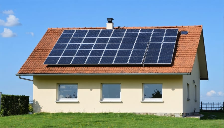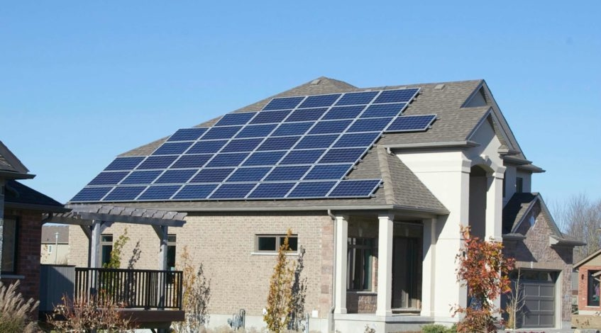
Grid Compliance Checklist for On Grid Solar System

When purchasing or operating an on grid solar system, it’s crucial to ensure compliance with grid codes, safety standards, and utility interconnection regulations, as they form the legal and operational basis for your system’s ability to connect to the power grid, export electricity, and maintain connectivity. Grid compliance protects personnel, safeguards revenue, prevents cascading blackouts, and ensures predictable system behavior during grid events such as frequency excursions, voltage sags, and islanding.

Standards, Certifications, and the Regulatory Environment On Grid Solar Systems Must Verify

Grid compliance begins with standards. When evaluating any on grid solar system, ask the manufacturer or supplier to submit evidence of compliance with your jurisdiction’s key technical standards and global type tests. In the United States, key reference standards include IEEE 1547 for interconnection and performance, as well as UL 1741 for inverter safety. For Europe and many global markets, EN 62116, EN 50549 / EN 50438, as well as IEC 61727, apply to the interconnection of utility-scale and distributed generation. Systems often require compliance with electromagnetic compatibility (EMC) standards, such as the IEC 61000 series, and they also require verification of anti-islanding effects.

Checklist for procurement:
1. PV inverter type test certificates (UL 1741, IEC 62109), including documented results of performance during anti-islanding effects, harmonics, and voltage and frequency deviations.

2. Grid code compliance declaration relevant to the target utility: including IEEE 1547, local grid codes, and any local technical requirements.

3. Harmonic and EMC reports showing total harmonic distortion (THD) levels and compliance with their limits.

4. Safety certifications (e.g., CE marking, CB Scheme certification) and documentation for electrical safety components.

5. Environmental and component standards, including IP ratings (IP65/IP66) for outdoor equipment, surge protector (SPD) ratings, and material compliance.
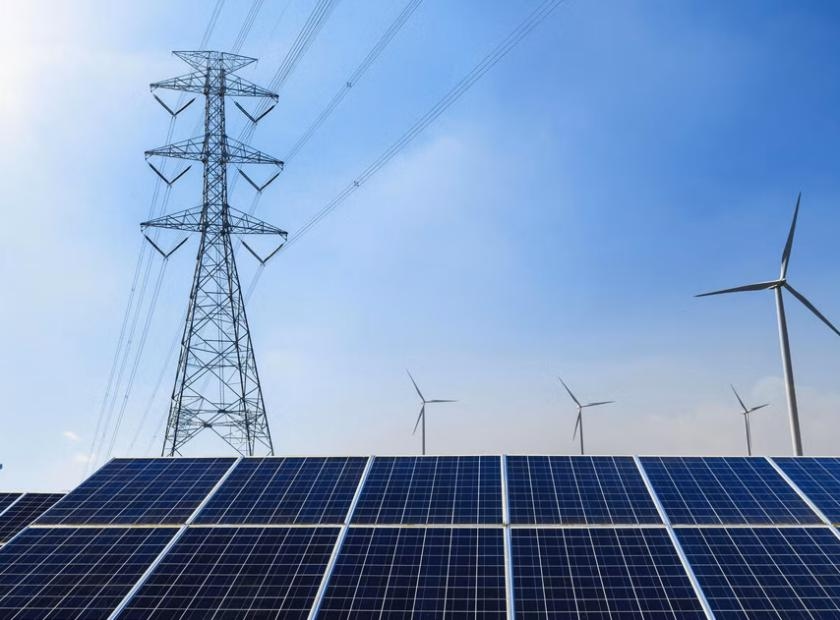
Standards, Certifications, and the Regulatory Environment On Grid Solar Systems Must Verify

Anti-Islanding, Fault Ride-Through, and Dynamic Grid Support

Anti-islanding and fault ride-through behavior are core features that determine a solar power plant’s ability to maintain connectivity during grid abnormalities. When purchasing a on grid solar system, verify its functional behavior and confirm the configurable parameter ranges.

Anti-Islanding: For safety and power quality reasons, utilities prohibit uncontrolled islanding. Therefore, on grid solar system suppliers are required to provide evidence of islanding resistance, including type test results in accordance with IEC 62116 or equivalent standards, as well as the specific test methods used.

Fault Ride-Through and Dynamic Support: Grid codes are increasingly requiring distributed generation (DGs) to be able to ride through short-duration voltage sags and frequency excursions, and to provide dynamic support.

Volt-Var and Volt-Watt Capabilities: Inverters in on grid solar systems must be able to inject/absorb reactive power and follow the Volt-Var curve or maintain a specified power factor.

Protection Device, Grounding, Isolation, and System Architecture Requirements for On Grid Solar System

Compliant on grid solar systems incorporate protection devices and system architecture to isolate faults and prevent damage to equipment. Therefore, ensuring that appropriate protective components and cabling are included on the procurement list is a top priority. This includes basic protection and isolation elements, such as PV string fuses or DC circuit breakers, appropriately rated DC isolators, and rapid shutdown capabilities that comply with regulations (e.g., US NEC 690.12). Utility interconnection breakers, anti-islanding relays, and grid protection relays should be sized appropriately for the inverter and transformer ratings. Grounding protocols should also comply with local standards (TN/TT/IT) and address lightning protection issues through site-specific grounding designs.

Protection Device, Grounding, Isolation, and System Architecture Requirements for On Grid Solar System

Commissioning, Testing, and Long-Term Compliance Management

Achieving grid compliance ultimately requires documenting commissioning and establishing an ongoing compliance system. Procurement contracts should require grid-connected solar system suppliers to provide complete test evidence, commissioning reports, and a regular review plan.

Commissioning and acceptance testing requirements include factory acceptance test (FAT) documentation for key equipment (inverters, transformers, and relays), showing test procedures and pass/fail results. The site acceptance test program encompasses insulation resistance, polarity checks, protective relay functionality testing, islanding prevention verification, low-voltage ride-through (LVRT)/high-voltage ride-through (HVRT) testing, as well as short-circuit and protection coordination testing. PV strings undergo IV curve testing and performance verification (using calibrated IV tracers) to confirm expected energy production and identify underperforming strings.

Long-term compliance and maintenance of on grid solar systems requires regular reverification of relay settings, meter calibration, and SPD replacement. Additionally, you should maintain an audit trail, and a change control process must govern any parameter changes. Power Dream’s on grid solar systems come with comprehensive commissioning support and signed FAT/SAT documentation.

Adherence to system testing, setup verification, and contract compliance support.

A comprehensive grid compliance checklist for on grid solar systems helps you move from supplier declarations to verifiable interconnection readiness. Adhere to the requirements and standards mentioned above during procurement and operation. Power Dream’s on grid solar systems meet all the compliance elements mentioned above: our inverters are type-tested for islanding protection, low-voltage ride-through/fast ride-through, and voltage-var control. Furthermore, our protection and metering packages meet common utility requirements. Our commissioning team provides FAT/SAT documentation, relay settings, COMTRADE logs, and structured O&M services to ensure long-term compliance and operational efficiency.
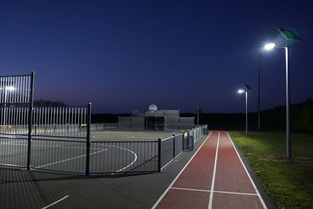
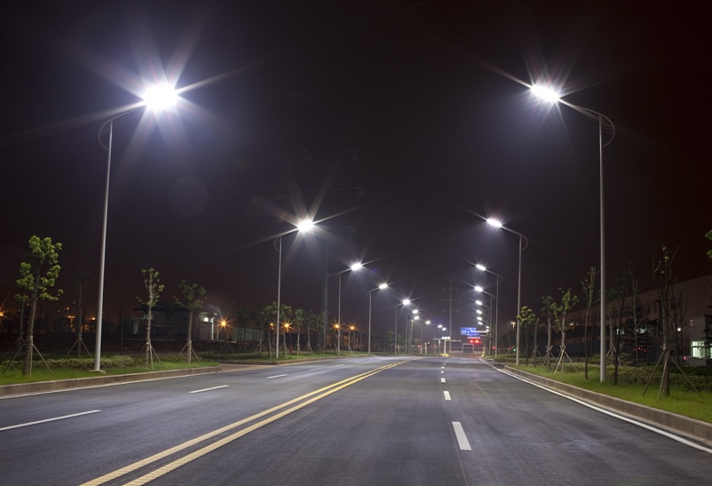
Uniformity and glare limitation techniques for installing solar street light on sidewalks

Sidewalk lighting does more than illuminate pedestrian paths; it also shapes public perceptions of safety and accessibility. As a solar street light manufacturer, Power Dream applies the same rigorous engineering to sidewalk lighting as we do to our commercial and residential solar products. Our goal is straightforward: to provide uniform, glare-limited lighting that saves energy, minimizes light spillage, and supports modern features such as remote monitoring and adaptive dimming. Therefore, when installing solar street light, we consider photometric planning, luminaire optical design, pole location and height, adaptive lighting controls, glare metrics and mitigation strategies, installation best practices, and operational considerations for long-term performance.

Photometric Planning for Solar Street Light

Achieving uniform sidewalk lighting begins with rigorous photometric planning. Uniformity is not an aesthetic objective; it is a measurable safety parameter, and visual and audio studies have shown that it correlates with reduced trip hazards and improved perceived safety. As a solar street light manufacturer, Power Dream conducts precise site surveys before each sidewalk project. Then, we perform photometric simulations to map lux levels for the sidewalk, adjacent curbs, and building facades.

Key indicators and design objectives include:

1. Average illuminance: The average horizontal illuminance (lux) at the pedestrian level. For typical sidewalks, the design target range is 5 to 20 lux, depending on urban density and usage.

2. Uniformity ratio: The ratio of minimum illuminance to average illuminance. A typical target for sidewalks is a uniformity ratio of U0 ≥ 0.4, or a ratio of average illuminance to minimum illuminance of no greater than 2.5; stricter uniformity ratios are more desirable in high-security areas or areas with dense retail concentrations.

3. Glare index: The limit used to control uncomfortable and disabling glare. For pedestrian environments, Power Dream uses a lower unified glare level and bug level to minimize uplighting and glare while allowing adequate backlighting to protect exterior walls.

Photometric Planning for Solar Streetlights

Determining the location, mounting height, and spacing of solar street light poles

The height, lateral offset, and spacing of solar street light poles significantly impact the achieved uniformity and glare. There is a trade-off between height and spacing. Increasing pole height increases light penetration and smooths the illuminance distribution, but it also widens the beam spread and may increase spillage onto adjacent buildings. Conversely, while lower mounts close to the ground provide higher luminous intensity, more poles are required to achieve the same uniformity. Power Dream typically recommends sidewalk mounting heights between 3.5 and 6.0 meters, depending on the specific site conditions.

Additionally, offsetting the luminaire from the curb toward the street alters the viewing angle and reduces glare into adjacent windows. For narrow sidewalks on either side of buildings, mounting the luminaire perpendicular to the curb with a slight lateral offset can reduce direct glare into storefront windows. Linear spacing should also be aligned with the desired average illuminance. A staggered layout can improve uniformity and reduce shadows cast by street furniture.

Determining the location, mounting height, and spacing of solar street light poles

Adaptive Control and Dimming Strategies

Uniformity is not a one-time achievement; it changes over time as luminaires age, dust accumulates on the optics, and vegetation grows. Smart controls combined with remote monitoring dynamically manage performance and reduce glare events. Therefore, it is crucial to purchase smart solar street lights with remote monitoring capabilities. Remote monitoring provides real-time insights into luminaire output, energy harvesting, battery charge status, and fault alerts. If the luminaire output decreases due to pollution or LED aging, an alert is triggered, and maintenance can be initiated before uniformity falls below a specified threshold. Adaptive dimming reduces glare during low-traffic hours and increases brightness when occupants are detected, balancing safety and energy efficiency.

Glare Limiting Technology at Installation

Glare is not only measurable but also has social impacts, with neighbors and business owners reacting strongly to perceived glare. Power Dream employs a layered glare control approach that integrates optics, installation practices, and human-centric operational controls.

The standardized glare levels used for indoor lighting also apply to outdoor lighting, with similar regulations that include discomfort thresholds and incremental thresholds for disabling glare. While there is no unified global outdoor standard, local thresholds are set based on specific circumstances. On the other hand, higher correlated color temperatures can increase visual glare, while warmer color temperatures (2700-3000 K) can reduce glare while maintaining color rendering. For residential sidewalks, Power Dream prefers warm white LEDs with a high color rendering index (CRI). For traffic areas with higher requirements for signage or facial recognition, a slightly cooler correlated color temperature (3500-4000 K) may be appropriate.

Installation, Commissioning, and Maintenance Practices

Good design must be accompanied by proper installation and maintenance. If installation tolerances are excessive or maintenance is reactive rather than preventative, uniformity and low-glare performance will be compromised. During the installation of solar street lights, we verify the verticality of the poles, the luminaire aiming angle, and the orientation of the photocell. Commissioning includes on-site lux measurements of the sidewalk at the target height and comparisons with simulated values. Dirt can also reduce effective lumen output, alter beam distribution, and impair uniformity. Local authorities can arrange for cleaning based on environmental conditions. Trees should be pruned appropriately to maintain sightlines and uniformity.

Ensure safe sidewalks with limited glare

The installation of uniform, low-glare sidewalk lighting encompasses every aspect, from product selection to ongoing operation. Power Dream’s approach combines precise photometric planning, asymmetric optics, carefully selected mounting geometry, adaptive dimming with remote monitoring, and standardized maintenance to ensure visual comfort and public safety. Municipalities and property owners considering this investment can purchase commercial-grade solar street lights designed for photometric consistency. If long-term uniformity and efficient operation are crucial, consider smart solar streetlights with remote monitoring.

Weatherproofing of off grid solar system kit: IP ratings, enclosures, and corrosion protection

When purchasing an off grid solar system kit, users typically prioritize the number of solar panels, battery capacity, and inverter power. However, a crucial factor in determining long-term uptime and warranty performance is the hardware’s resistance to weather and corrosion. Even an appropriately sized system can quickly fail if installed in a humid coastal yard, a rooftop subject to monsoon winds, or a dusty desert plain, if the enclosure, connectors, and materials are not of standard quality. Poor weatherproofing increases the need for repairs, shortens module life, and often voids the warranty.

The Significance of IP and NEMA Ratings for Off Grid Solar System Kit

Selecting the appropriate IP rating is a primary consideration when purchasing an off grid solar system kit. The globally recognized IP (Ingress Protection) standard (IEC 60529) and the associated NEMA/UL ratings represent the enclosure’s ability to resist solid objects, water, and corrosion. Therefore, buyers typically map each module to the appropriate IP rating based on the intended installation.

IPxx: A two-digit number. The first digit (0-6) indicates protection against solid objects (dust), and the second digit (0-9K) indicates protection against liquids. For example, IP65 means dustproof (6) and protected against low-pressure water jets (5). IP66 means dustproof and protected against high-pressure water jets (6); IP67 means short-term immersion; IP68 means long-term immersion to a specified depth. IP69K adds resistance to high-pressure, high-temperature washdowns (suitable for industrial environments).

NEMA ratings (US): NEMA 3R (rain and snow weather), NEMA 4/4X (washdown and corrosion resistant), NEMA 6, NEMA 12 (dustproof/industrial). NEMA 4X is often used in coastal or corrosive environments because it specifies resistance to corrosion. UL50/UL50E specifies the enclosure structure and certification.

The Significance of IP and NEMA Ratings for Off-Grid Solar System Kits

Protection level requirements for each component in the off grid kit:

PV combiner box and DC junction box: Minimum protection level is IP65; IP66 or NEMA 4X is preferred in coastal or monsoon climate areas.

Inverter/Inverter Charger: Many outdoor string inverter models are rated IP65/IP66. Ensure they are housed in a weatherproof enclosure for outdoor installations. For small off-grid inverter chargers installed on exposed rooftops or free-standing poles, ensure they meet at least an IP65 rating, with UV-resistant housing and corrosion-resistant fasteners.

Battery Enclosure: Both lithium-ion and lead-acid batteries typically require a well-ventilated enclosure. For sealed lithium-ion modules, an IP54–IP66 rated enclosure can provide controlled ventilation while protecting the electronics. For flooded lead-acid batteries, the enclosure must provide ventilation and drip protection, rather than a fully sealed immersion rating.

Electronics and Controllers: MPPT charge controllers and monitoring gateways can be IP65-rated or housed in a small weatherproof enclosure. If installed outdoors, ensure the enclosure has pressure equalization vents to prevent pressure buildup.

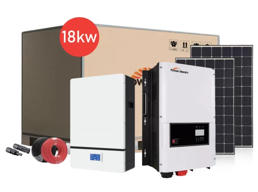
18KW off grid kit

Enclosures, Vents, and Pressure Equalization for Off Grid Solar System Kit

A weatherproof enclosure is more than just a pressurized box. Effective enclosure design should consider factors such as drainage, condensation, pressure differentials, UV exposure, and ease of maintenance. Consider these features when selecting an enclosure for your off grid solar system kit.

Pressure-Equalizing Vent:
Sealed enclosures experience pressure changes in response to temperature fluctuations. If pressure is not balanced, these pressure cycles can force moisture to penetrate the seal. High-quality vents, however, allow air to pass while preventing liquid water from entering. For outdoor charge controllers or small combiner boxes, it’s crucial to install the vent on the enclosure cover or sidewalls, especially in humid climates, where moisture intrusion is a primary failure mode.

Drainage and Sloped Covers:
Select enclosures with sloped covers or integrated drip edges for rapid drainage. Gaskets should be compressed evenly; choose molded, fixed gaskets rather than glued or loose-fitting gaskets, as these can easily degrade or become compressed during repairs.

Mounting and Clearances:
The enclosure should be installed with a small gap behind the backplate to facilitate air circulation and prevent heat soak. Do not mount the cabinet of an off grid solar system kit directly on highly conductive surfaces, as these surfaces may conduct heat or moisture, potentially compromising the system’s performance. In coastal areas or rainy climates, install the cabinet under an eave or use an additional weatherproof cover to protect the top while allowing for air circulation.

Desiccant, Heater, and Thermostatic Control:
For humid areas, place removable desiccant packs inside smaller cabinets. For larger battery/inverter compartments, consider using a thermostatically controlled, low-wattage heater to prevent condensation at night. In cold climates, heaters prevent the internal temperature from dropping below the recommended operating range for the batteries, thereby preventing moisture from being generated when the equipment is heated.

Corrosion-Resistant Materials, Coatings, and Fasteners

Corrosion is a hidden killer for off grid solar system kits, particularly in areas near saltwater or in industrial environments. Therefore, it’s essential to ensure the appropriate materials and coatings are in place to significantly extend the lifespan. The following are some functional, corrosion-resistant materials to consider when selecting an off-grid solar system kit.

Construction Materials and Coatings: Aluminum is a lightweight material that is anodized for its inherent corrosion resistance. Suitable for module frames, junction boxes, and some small enclosures. For coastal locations, use marine-grade anodized steel with a thick oxide layer for enhanced corrosion resistance. When joining aluminum to steel, be mindful of galvanic corrosion; use non-conductive washers or coatings to isolate the dissimilar metals.

Hot-dip galvanized steel is the standard for racking structures. If your off grid solar system supplier offers options such as Aluzinc, Magnelis, or S350GD, ensure they meet ISO 1461:2009 or equivalent standards for hot-dip galvanized steel, with a minimum zinc coating. These materials offer improved corrosion resistance. For the harshest coastal environments, consider a two-layer system.

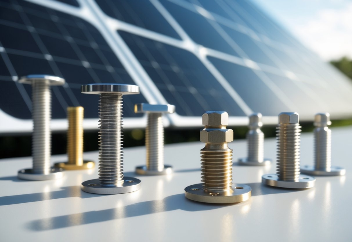
Stainless steel fasteners: For coastal installations, use A4/316; A2/304 is acceptable in inland areas but corrodes more rapidly in coastal locations. Specify the material grade and mechanical rating, and avoid using mixed metal fastener kits.

Corrosion-resistant materials, coatings and fasteners

Climate-Specific Recommendations and Best Installation Practices

Weather conditions vary significantly from region to region. The following are practical recommendations for specific climates from Power Dearm, an off grid solar system supplier.

Coastal and marine environments:
Use A4/316 stainless steel fasteners or a double-sided system (hot-dip galvanizing + polyester powder coating). For hot-dip galvanized rails, specify Aluzinc/Magnelis or high-weight zinc with a double-sided coating. Additionally, use conformally coated PCBs and sealed connectors, and ensure regular maintenance intervals of every 6-12 months to inspect fasteners and remove salt deposits.

Tropical monsoon climates (high humidity, heavy rain):
Outdoor enclosures must meet an IP65 or higher rating and use pressure-equalizing vents to control condensation. Use stainless steel hardware and a UV-resistant coating to prevent mold and biodegradation. Opt for elevated mounting and avoid installation in areas with stagnant water; route cables indoors whenever possible.

Arid, dusty deserts and high-sand areas:
Use a dust-resistant enclosure (IP65/IP69K, washdown compatible) and select filters for vents. Consider fanless designs to reduce dust ingress.

Choose a Weatherproof Off Grid Solar System Kit

When selecting an off-grid solar system kit, be sure to check the IP/NEMA ratings of the components, the manufacturer’s testing (including IP/UL certification, salt spray, and UV exposure), and the rugged materials and fastening specifications. Furthermore, if necessary, tailor your selection to suit local climate conditions (coastal, tropical, desert, and cold climates).

Seasonal Production Overview: Monthly Home Solar Systems Production Expectations

Purchasing home solar systems involves more than just selecting solar panels and signing a contract. Even before that, it’s crucial to predict how much electricity your rooftop can reliably produce each month during the summer peak and winter trough. From the perspective of a home solar system supplier, we’ll provide a practical, engineering-based framework for converting system capacity into monthly kilowatt-hours of electricity generation, accounting for seasonal and site variations. This will allow you to evaluate energy generation estimates and ensure the data you receive is comparable.

Capacity and Yield of Home Solar Systems

Before we discuss output, let’s clarify two commonly confused metrics: system capacity and energy generation. The capacity of a home solar system, expressed in kW (for example, 5 kW or 6 kW), represents the instantaneous peak DC power the array can generate under standard test conditions. Energy generation, expressed in kilowatt-hours (kWh), represents the actual amount of electricity the system produces over a period of time (for example, 18 kWh/day or 540 kWh/month).

When evaluating home solar system quotes, use the following simple conversion and sizing formula:
Daily energy production (kWh/day) ≈ System capacity (kW) × Peak sunshine hours (PSH/day) × System efficiency

Where:
PSH equals the average number of hours of sunshine at a sunshine intensity of 1,000 watts per square meter.

System efficiency takes into account actual losses, including inverter efficiency, temperature, cabling, and other factors. For modern rooftop systems, a good rule of thumb is an efficiency factor of 0.75-0.85, which accounts for all losses. For example, if the average PSH in your area is 4.0 in June, and you have a 6 kW solar home system with 80% efficiency, your daily energy production will be approximately 19.2 kWh/day. Therefore, when requesting a quote from a solar home system supplier, provide your expected monthly electricity consumption and clearly state the assumptions. This transparency ensures comparable plans.

Seasonal solar resource for home solar systems

Seasonality is the single largest factor contributing to monthly energy production differences among home solar systems. Your location’s solar resource (irradiance) determines the number of peak sunshine hours you receive each month.

First, sun angle and day length play a role. In temperate climates, the longer summer days and higher sun angles result in higher peak sunshine hours (PSH) from June to July. Conversely, the shorter winter days and lower sun angles cause a sharp drop in PSH from December to January. In equatorial or near-equatorial climates, day length and sun angle vary less, resulting in more stable monthly energy production throughout the year.

Another factor is weather patterns: regional cloud cover, rainy seasons, and atmospheric aerosols can reduce the effective PSH in a given month. Because the thermal efficiency (PSH) of solar photovoltaic systems can vary by a factor of 2-3 between summer and winter in northern temperate regions, monthly energy production in the same calendar year can typically be 150% to 300% of winter energy production. For example, in sunny southern states, a 6 kW system might generate approximately 1,000 kWh in July, but only 250-350 kWh in December.

Seasonal solar resource for home solar systems

Design Factors Affecting Monthly Energy Production

The monthly performance of a home solar system depends not only on the resource, but also on the design. Subtle design choices can significantly alter the monthly energy production curve, and this is often affected by the season.

Tilt and Aspect:
A solar array facing south (in the Northern Hemisphere) maximizes annual energy production. At higher latitudes, tilting the panels helps better capture winter sunlight. A fixed tilt, consistent with the latitude, provides consistent energy production year-round. If your goal is to maximize summer energy production, lower the tilt in areas slightly below the latitude. If winter energy production is your priority, increase the tilt in areas above the latitude.

Shading:
Shading from trees, chimneys, or nearby buildings can significantly impact monthly energy production, as it is particularly detrimental during months with lower sun angles. Additionally, microinverters or power optimizers can mitigate the effects of shading at the module level, maintaining higher energy production during partially shaded months compared to single-string inverters.

Module Technology and Temperature Coefficient:
Some high-efficiency modules perform better on hot rooftops. If your area experiences high temperatures, choose modules with a lower temperature coefficient to avoid performance degradation during the summer.

Design Factors Affecting Monthly Energy Production

Monthly Losses, Derating, and Actual System Efficiency Assumptions

Accurate monthly energy production estimates require an honest calculation of actual losses. When calculating energy production, apply a conservative system efficiency factor to account for accumulated losses. Typical loss categories and representative ranges include:
Inverter Efficiency: 96-99% at rated load.
Contamination (dust, pollen): 1-6%. Dirt accumulates more rapidly during dry seasons.
Temperature Losses: 3-12%, depending on the module temperature coefficient and local ambient temperature.
Mismatch and Cabling Losses: 1-3%.
Performance Degradation Over Time: Approximately 0.5-1% per year. System Downtime and Maintenance: If an inverter requires a firmware update or a grid outage occurs, downtime and maintenance, while not significant, is not zero.

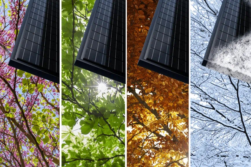
For a well-designed residential system, a reasonable overall planning de-rating factor is 0.75-0.85 (i.e., 15-25% total losses). Note that losses are not constant from month to month: temperature and pollution effects often exacerbate summer losses or dry season pollution in arid regions, while shading from deciduous trees disproportionately reduces winter performance.

Practice Proper Seasonal Planning

Understanding your monthly power generation expectations can directly guide decisions about energy storage and load management. If your home solar system generates more power in the summer and less in the winter, your energy storage requirements and power output behavior should reflect this seasonality.

Storage Capacity: If you want to shift excess daytime power to the evening, select battery capacity based on nighttime autonomy, not seasonal transition capacity. Seasonal gaps can be addressed through grid feeds or demand-side reductions. Use your generation curve to determine how many kilowatt-hours need to be shifted daily and select battery capacity accordingly. Additionally, it’s important to align your primary load with peak-production months or times. Time-of-use pricing can make midday exports profitable in some regions, while in other markets, you may prefer to generate electricity for your own consumption.

Calculate your monthly electricity usage and purchase the right system.

Collect your monthly electricity usage, set a target for your own consumption, and request a complete 12-month electricity meter from your home solar system provider. Then, evaluate your options based on your monthly electricity consumption. This rigorous approach can transform seasonal uncertainty into a reliable energy plan, giving you confidence in your budget and your life.

Hidden factors leading to the rising solar battery cost

Overall data for residential and commercial energy storage has raised concerns among many users. Fluctuations in installation prices and inconsistent quotes from suppliers have left customers wondering why a seemingly mature technology continues to experience cost fluctuations. The rising solar battery cost often involves less obvious drivers, not just the obvious battery price, but also a range of factors, including materials, manufacturing, regulation, logistics, and market factors, which all contribute to the rising costs.

Raw Materials and Battery Chemistry Pressures Drive Solar Battery Costs

One of the most significant hidden drivers of solar battery costs is the raw material supply and the specific battery chemistry. Modern batteries used with solar batteries primarily utilize lithium-ion chemistries: lithium iron phosphate (LFP), nickel manganese cobalt (NMC), and variations in between. Each chemistry relies on different commodity inputs: lithium, nickel, cobalt, manganese, graphite, and electrolyte precursors. Fluctuations in the prices of any of these inputs directly impact battery pack costs.

For example, when nickel or cobalt prices rise due to production disruptions or EV demand, NMC-based battery packs can become more expensive. Conversely, LFP contains no nickel or cobalt, making it typically cost-effective when these metals rise in price. However, lithium iron phosphate requires high-purity iron phosphate raw materials and specialized manufacturing adjustments. Regional bottlenecks have emerged in the supply of graphite for anode production. The choice of synthetic versus natural graphite also affects cost and yield. Furthermore, lithium conversion capacity is highly capital-intensive and can become a bottleneck. These imbalances are not always reflected in manufacturers’ quotes, but they determine the marginal price of additional capacity.

Raw Materials and Battery Chemistry Pressures Drive Solar Battery Costs

Manufacturing Capacity, Factory Economics, and Volume Effects

A second hidden pressure on solar battery costs comes from manufacturing costs. Unlike commercial photovoltaic batteries, battery production is capital-intensive and yield-sensitive. Battery manufacturing requires gigafactory-scale investments in electrode coating lines, battery formation chambers, drying rooms, and high-precision assembly. New factories take years to come online; therefore, rapid demand growth outstrips existing capacity, forcing manufacturers to increase capital utilization and allocate batteries to the most profitable customers. This allocation dynamic raises the marginal price for buyers without scale or long-term contracts.

Furthermore, solar batteries must meet strict quality tolerances and formation cycles to ensure stable battery aging. Yield issues on early production lines—uneven coatings, electrode misalignment, or formation anomalies—can result in scrap. High initial defect rates can increase the actual cost of solar batteries until process control stabilizes. Even after production lines mature, incremental capacity expansions often use older equipment or third-party components, which can suppress yield and increase the cost per kilowatt-hour.

Supply chain disruptions, logistics, and policy frictions drive up solar battery cost

Logistics and trade policies are powerful hidden drivers of solar battery costs. Batteries and modules are heavy, regulated commodities. Freight rate fluctuations, port congestion, and trade policy changes can add hundreds of dollars to the landed cost of each battery stack. Furthermore, batteries are classified as hazardous goods under IATA/IMDG regulations, which increases packaging, documentation, and carrier costs compared to many other electronic products. These subtle freight and compliance costs can significantly impact the final price of solar cells delivered to installers and end customers.

Trade and tariff policies further complicate the situation. Anti-dumping duties, import tariffs on batteries or chemical precursors, or country of origin rules can unpredictably increase landed costs if new measures impact supply chain nodes. During periods of geopolitical pressure or sanctions, solar battery suppliers may reroute supply through the more profitable secondary market, and manufacturers typically pass these costs on. For global solar energy storage buyers comparing quotes from different suppliers, differences in shipping terms and their treatment of tariffs often result in significant line-item differences.

Supply chain disruptions, logistics, and policy frictions drive up solar battery cost

Regulatory, Testing, and Safety Compliance Burdens

Regulatory compliance carries significant hidden costs, increasing solar battery costs beyond raw material and factory costs. Batteries must meet increasingly stringent safety, shipping, environmental, and recycling regulations. Obtaining certification to local standards—such as UL 1973 and UL 9540A in the US, UN38.3 for shipping, CE and WEEE in the EU/UK, and CSA standards in Canada—requires laboratory testing, design changes, and documented factory processes.

Furthermore, shipping regulations (UN38.3) require rigorous testing of batteries and battery packs, while airlines or freight carriers require additional documentation and packaging, which can increase shipping costs. The growing emphasis on secondary use and recycling creates new compliance burdens, or the need to internalize end-of-life costs. These obligations increase manufacturing costs and are often reflected in the final solar battery cost in the form of recycling fees or service surcharges.

Multiple Factors Influencing Costs

The rising solar battery costs are the result of a complex interplay of factors: the commodity cycles of lithium and metals, capital and revenue realities in manufacturing, logistics, and tariffs, rising energy and chemical prices, and intense competition for demand from other large buyers. Each of these factors contributes to costs, and these costs can be easily overlooked when focusing solely on battery pack prices.

Comprehensive analysis of factors that determine the solar battery price

Our services range from purchasing solar battery raw materials and battery chemistry to system integration, installation, certification, and service contracts. From a solar battery supplier perspective, we categorize cost drivers into component-level inputs (batteries, modules, and battery management systems); system-level specifications (available kilowatt-hours, round-trip efficiency, cycle life, and warranty); and soft costs. Furthermore, we demonstrate how market forces (brand, scale, location, incentives, and total lifecycle cost) can influence the effective price of your solar battery purchase and the value you receive. Finally, we translate technical specifications into purchasing metrics, such as available $/kWh and levelized cost of energy storage, allowing you to compare options across suppliers and regions objectively.

Battery chemistry and raw materials are cost drivers of solar battery price.

Battery chemistry is the most important component-level determinant of solar battery price. Lithium-ion batteries make up the vast majority of modern stationary batteries. However, there are also important subtypes within lithium-ion batteries, such as lithium iron phosphate (LFP), nickel manganese cobalt (NMC), and nickel cobalt aluminum (NCA), which influence both upfront costs and long-term economics.

First and foremost, raw materials are crucial. The prices of nickel, cobalt, and manganese significantly impact NMC and NCA batteries. Cobalt price fluctuations increase NMC costs and supply chain risk premiums. LFP uses iron and phosphate, which are lower-cost and more abundant. Therefore, LFP-based batteries generally offer a lower cost per kilowatt-hour of solar cells and greater price stability. Secondly, their energy densities differ. NMC/NCA batteries offer higher energy density per kilogram for the same capacity and a smaller footprint, which can reduce balance-of-system and transportation costs, but typically come with higher raw material prices.

In addition to chemical composition, battery specifications and module structure are also crucial. Prismatic batteries are mechanically more robust and easier to assemble into modules, while pouch cells maximize packaging density but require careful thermal and mechanical management.

Battery chemistry

Performance Metrics Affecting Cost and Value

These metrics significantly impact the price per kilowatt-hour of active solar batteries. Two batteries with a rated capacity of 10 kWh can have very different economics depending on their usable capacity, depth of discharge (DoD), round-trip efficiency, and decay rate.

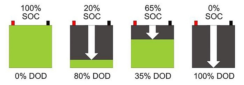
Depth of discharge (DoD) is the percentage of nominal capacity that can be safely used per cycle. A battery pack at 90% depth of discharge provides more useful energy than one at 50%, thus reducing the effective solar battery cost per usable kilowatt-hour (kWh) even at a similar nominal cost per kilowatt-hour (kWh). Round-trip efficiency further impacts energy output: a 95% efficient system loses 5% of its energy per cycle, while an 85% efficient system loses 15%, which is important for solar cell users in daily cycling.

Cycle life and degradation curves also determine the duration of usable capacity. Manufacturers typically specify the number of cycles as a percentage of the original capacity. Batteries with higher upfront costs but slower degradation can reduce lifecycle costs because they require less frequent replacement. Therefore, it is important to calculate not only the nominal cost but also the usable cost over the expected lifetime, taking into account degradation and the expected number of cycles per year.

Depth of discharge (DoD)

The impact of battery management, safety systems, and certification on solar battery price

The battery management system (BMS), thermal management, and safety architecture also have a substantial impact on solar battery prices and determine risk exposure and operational limitations. A complex BMS increases upfront costs, but it can protect assets, enable precise state-of-charge (SoC) control, support cell balancing, and provide telemetry, thereby reducing operations and maintenance (O&M) expenses.

BMS features that need to be evaluated include cell-level monitoring, overcharge/discharge protection, battery balancing methods, software-controlled depth-of-discharge limiting, and rapid fault isolation. Meeting certifications and safety testing also adds to the price. For many installations, compliance with UL 1973, UL 9540A (thermal runaway testing), IEC 62619, and local grid interconnection or fire regulations is essential. Obtaining and documenting these certifications requires laboratory testing and engineering changes, and reputable solar battery manufacturers factor these costs into the price of their solar batteries. Conversely, a system without comprehensive certifications may initially appear cheaper, but it can be less secure and carry significant risks.

Balance of system, inverter compatibility, and installation labor costs are also important.

The price of the solar battery is only part of the cost of installing a solar battery. Balance-of-system (BOS) components, including bidirectional inverters, AC/DC coupling equipment, switchgear, circuit breakers, enclosures, wiring, and energy management software, typically represent a significant portion of the total system cost. In residential projects, their cost often matches or exceeds that of the battery modules.

Bidirectional inverters must be compatible with the battery chemistry and BMS communication protocol. Some solar battery suppliers offer integrated inverter-battery systems. This integrated solution often reduces the overall BOS cost and simplifies warranty claims, but may limit supplier selection and future upgrades. Therefore, when purchasing solar battery hardware, clarify the scope of integration and whether the quote includes the inverter, monitoring gateway, and commissioning.

Installation labor is a significant soft cost and varies by location and permit complexity. In highly regulated regions, permitting, inspection, and interconnection fees can significantly increase the cost of solar cell installation. For large commercial projects, crane access, grounding, fire suppression, and isolation from other electrical infrastructure add complexity. Space and civil engineering are also considerations, for outdoor rack-mounted systems, foundations, concrete pads, and enclosures add costs. For indoor installations, HVAC conditioning, seismic restraints, and firewall isolation can also increase costs.

Market Dynamics, Brand Premiums, and Supply Chain Impacts

Market forces and supplier reputation can influence the price of your solar batteries. Brand premiums exist for a variety of reasons: proven field performance, local support networks, and lower long-term risk. Premium brands typically have higher upfront prices, but they can reduce the risk of unexpected failures and typically offer better warranty enforcement. Tariffs, shipping costs, factory capacity, and exchange rates can all lead to regional price differences. For example, cells manufactured in Asia and shipped to North America or Europe face additional costs, including shipping, tariffs, and inland logistics fees, which can increase solar cell costs. Even geopolitical unrest or raw material shortages can cause prices to spike dramatically. Finally, consider second-order market effects. The growing demand for electric vehicles and stationary energy storage will spark competition for battery-grade raw materials, impacting prices.

Making the Right Sourcing Decisions

The solar battery price you see on a quote is just one starting point, not the whole picture. To make a sound purchasing decision, it is necessary to translate technical specifications into commercial metrics, such as the cost per kilowatt-hour available over the expected lifetime, the levelized cost of energy storage, the expected number of annual cycles, and the warranty period. Then, using standardized metrics, you can evaluate various quotes side by side during the purchase process to select the solar cell that best suits your needs.

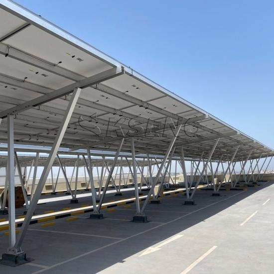
How to choose solar panel mounting bracket for carport electric vehicle charging station?

Choosing the right solar panel mounting bracket for a carport-type EV charging station requires careful consideration of site loads, module layout, foundation type, and operational requirements. The Power Dream solar carport mounting system features a modular structure that allows for vertical or horizontal PV panel installation, supports tilting of 5° to 15°, and can be installed on reinforced concrete or pile foundations. Power Dream utilizes cold-rolled S235JR/S355JR steel coils that comply with EN 10025 and are hot-dip galvanized according to ISO 1461:2009. S350GD galvanized steel coils that comply with EN 10326 or equivalent are also available. This meets the requirements for solar panel mounting brackets in carport-type EV charging stations.

Determining the Material and Corrosion Resistance of the Solar Panel Mounting Bracket

The material choice determines the service life and maintenance costs of the solar panel mounting brackets on the carport. Busy public charging stations, frequently exposed to vehicle salt spray, urban pollution, and occasional de-icing splash, require robust corrosion protection. Power Dream’s solar carport mounting systems utilize cold-rolled S235JR or S355JR steel coils (EN 10025) hot-dip galvanized according to ISO 1461:2009, providing a uniform, metallurgically bonded zinc layer. For corrosive coastal or industrial environments, you can choose S350GD galvanized steel coils according to EN 10326 or corrosion-resistant substrates such as Aluzinc, Magnelis, Corrender, or Posmac. These coatings provide enhanced barrier and cathodic protection, specifying a minimum zinc or equivalent coating mass of 275 g/m², ensuring decades of service life with low maintenance costs and meeting relevant certification requirements.

Determining the Material and Corrosion Resistance of the Solar Panel Mounting Bracket

Consider the Structural Design and Environmental Loads of the Solar Panel Mounting Bracket

When selecting a carport solar panel mounting system, it must be able to safely withstand environmental loads while providing adequate clearance for the vehicle and charger. First, define the design loads according to local building codes. For example, US projects refer to ASCE 7 for wind and seismic load design; European projects refer to Eurocodes; and Indian projects refer to IS Codes. The mounting system’s cross-sectional area, component dimensions, and connections must be verified through structural analysis based on these site-specific loads.

Key structural considerations include panel orientation, effective tributary area per module, and tilt angle. In certain latitudes, a higher tilt can improve energy capture, but it increases wind lift and snow accumulation, increasing the required mounting stiffness and foundation size. For urban carports where clearance height is a concern, designers should achieve a minimum of 2.2–2.4 meters.

Furthermore, you must ensure that the mounting system maintains module clamping force and alignment under dynamic loads. Use lock washers or pre-torqued nuts where applicable, and design connectors to allow for simple on-site replacement without disturbing adjacent modules. For locations with significant temperature fluctuations, provide expansion joints or slots in the rails. For long spans, include mid-span supports or stronger profiles to prevent excessive deflection. If the carport utilizes a multi-bay modular array, consider modular column spacing that matches the bay dimensions to reduce material waste and simplify installation.

Foundation and Mounting Options

Choosing the appropriate solar panel mounting bracket for a carport electric vehicle charging station also depends on local soil conditions, budget, and installation speed. Power Dream’s solar carport mounting systems are designed for reinforced concrete pad foundations as well as driven or bored pile foundations.

Reinforced concrete provides stable support and is suitable for sites with good bearing capacity and surface preparation. To prevent corrosion, we hot-dip galvanize or use stainless steel for anchor bolts, and we protect the baseplate-concrete interface with a coating or sleeve to prevent water seepage. For pile foundations, we prefer screw piles, driven steel H-piles, or bored piles on sites with poor surface soil or limited excavation. Screw piles speed installation and reduce concrete usage. They can be load-tested on-site and provide immediate load-bearing capacity. For carport charging stations, we pre-assemble the main beams and tracks into manageable modules and then hoist them into place, rather than assembling numerous small components at height.

Determining PV Panel Layout and Orientation

The availability and usability of a charging carport depend not only on the solar panel mounting brackets but also on the PV panel layout and orientation. Power Dream’s flexible solar carport mounting systems allows panels to be installed vertically or horizontally, with tilts of 5° to 15° to the south or east. Leverage these degrees of freedom to optimize energy production and address site constraints.

For customers in the Northern Hemisphere, a south-facing array (or a north-facing array in the Southern Hemisphere) maximizes peak energy production. An east-facing array better suits morning charging patterns. For public or workplace charging with irregular arrival times, consider an east-west split array to balance power generation throughout the day. Both horizontal and vertical mounting options affect shading and panel spacing. Vertical layouts allow for closer integration with lampposts or signage, while horizontal layouts reduce wind and facilitate panel replacement. The electrical design should also consider string length, MPPT allocation, and distance from the EV charger and inverter. During the expected lowest temperature, you should keep the string voltage within the inverter input range to avoid overvoltage. Finally, the design should consider future expansion by reserving spare capacity in the column base and planning routing for additional cabling.

Solar Carport Mounting Systems

Suitable Mounting Brackets for Carport-Type Charging Stations

Selecting the appropriate solar panel mounting bracket for a carport-type EV charging station requires a balance between structural design, material science, electrical integration, and construction practicality. Power Dream provides solar panel mounting brackets certified to relevant standards. Under standard conditions, they utilize hot-dip galvanized, cold-rolled S235JR/S355JR steel compliant with ISO 1461:2009, as well as S350GD/Aluzinc/Magnelis steel for harsh environments, or anodized aluminum alloy. We also select the appropriate hardware based on site requirements, ensuring ISO-compliant A2-70 stainless steel or coated carbon steel. We also provide comprehensive certification, FAT/SAT testing, and a comprehensive warranty. Furthermore, engineers use energy modeling and shading analysis to confirm panel orientation and tilt, ensuring safe, long-term electric vehicle charging operations.

Why do monocrystalline PV modules have excellent low-light performance?

Monocrystalline PV modules often outperform other modules in low-light conditions, whether on an overcast morning or a cold winter day. Monocrystalline PV modules combine purer silicon, advanced cell structure, and optimized optical surfaces to convert a higher proportion of diffuse and low-irradiance light into useful electricity. First, the crystal quality and doping uniformity of monocrystalline silicon wafers reduce electrical losses and enable better carrier collection in low-light conditions. Second, cell and surface engineering enhance light absorption and maintain efficiency in low-angle and diffuse light. Third, module- and system-level designs preserve the advantages of cells, enabling installed solar panel systems to generate higher energy even under non-ideal conditions.

The advantages of crystal quality and semiconductor physics in monocrystalline PV modules

The core of excellent low-light performance lies in material quality. The core of monocrystalline PV modules is monocrystalline silicon ingots, whose wafers have extremely uniform atomic order and far fewer grain boundaries than multicrystalline silicon grains. These grain boundaries act as microscopic traps for photogenerated carriers, so fewer grain boundaries mean lower recombination losses in monocrystalline batteries. Under low irradiance conditions (where fewer carriers are generated), preserving each carrier becomes even more critical. Therefore, the advantages of monocrystalline silicon are more pronounced under cloudy skies or in early morning sunlight.

In addition, many monocrystalline PV module manufacturers use advanced processes to control doping concentration and lifetime, thereby increasing the diffusion length of minority carriers. When the diffusion length exceeds the cell thickness, carriers generated far from the pn junction can still reach the junction and generate current. Because the generated carrier density is lower at this point, better carrier collection results in a higher short-circuit current compared to competing batteries.

The advantages of crystal quality and semiconductor physics in monocrystalline PV modules

Battery Structure and Surface Engineering for Monocrystalline PV Modules

Materials are necessary but not sufficient. Battery structure and optical engineering are crucial for translating silicon’s advantages into practical output. Many monocrystalline PV modules utilize advanced cell structures such as PERC, heterojunction, TOPCon, or staggered back-contact designs. These structures reduce surface recombination, trap light internally, and allow for a longer optical path within the silicon wafer, thereby increasing the absorption of oblique and diffuse photons.

Surface treatment is also crucial. Anti-reflective coatings and textured surfaces can reduce reflection losses over a wide range of angles. At low solar angles or in diffuse lighting, modules that maintain low reflectivity will capture more photons. Furthermore, light-harvesting technologies such as rear reflectors, microtexturing, and specially designed rear passivation reflect weak rays into the silicon wafer, giving edge photons a second chance to generate charge carriers. Bifacial monocrystalline PV modules are particularly noteworthy. Because bifacial modules receive usable energy from both the front and back sides, their gain is higher under diffuse or ground-reflected light conditions.

Battery Structure and Surface Engineering for Monocrystalline PV Modules

Electrical Properties and Current-Voltage Behavior Under Low Irradiance

Low-light performance is not only reflected in optical aspects, but also in electrical aspects. The electrical properties of monocrystalline PV modules under low irradiance conditions determine whether captured photons can be converted into usable power. Two of the most important parameters are the scaling of the short-circuit current (Isc) and the maintenance of the fill factor (FF).

Under ideal conditions, Isc has a roughly linear relationship with irradiance. However, actual modules can exhibit deviations due to shunting paths and recombination effects. High-quality monocrystalline batteries, due to their lower leakage current and longer carrier lifetime, are better able to maintain Isc in low-light conditions. Fill factor is also crucial; batteries with high internal series resistance or severe recombination effects will experience a reduction in fill factor in low-light conditions. However, monocrystalline batteries with low series resistance and good passivation processes can maintain fill factor, resulting in higher power output even with reduced Isc. Furthermore, open-circuit voltage (Voc) is less sensitive to irradiance but is affected by temperature. Voc is higher in low-light conditions and on cool mornings, helping maintain the module operating point and improving MPPT efficiency.

Preserving the Advantages of Low-Light Rooftops

Even the best monocrystalline PV module can underperform if poorly designed at the module and system levels. Good practices can preserve the advantages of the batteries and maximize the capture of low-light energy. First, keep the string voltage within the MPPT operating window and minimize mismatch losses. Mismatch becomes particularly critical in partial shading or when the modules are oriented differently. At the same time, designers should use string layout and module matching to ensure that the MPPT algorithm operates in the most efficient IV region under low irradiance. For systems affected by shading, microinverters or MLPE can maintain the single-module advantages of monocrystalline batteries by independently extracting maximum power from each module.

Secondly, well-placed bypass diodes can prevent localized hotspot losses under partial shading conditions. They can also prevent a sharp drop in power across the entire string when a partial area is shaded. Monocrystalline delivers its best performance when even illumination evenly lights the batteries. Finally, you must also use a charge controller or inverter with reliable low-irradiance MPPT performance. When combined with monocrystalline modules, which offer clearer IV characteristics in low-light conditions, this can result in higher daily energy yields.

Finally, the tilt, orientation, and height of the installation determine the amount of diffuse and reflected light reaching the modules. For example, in Thailand, a slight tilt can reduce midday overheating while capturing more diffuse light in the morning and evening. In southern Argentina, optimizing the tilt for the winter months can improve low-sun-angle performance. For solar panel systems, consult your monocrystalline PV module supplier for installation guidance to maintain the advantages of low-light conditions on site.

Preserving the Advantages of Low-Light Rooftops

Site Examples and Recommendations for Thailand and Argentina

Both Thailand and Argentina have areas where diffuse light, seasonal variations, or high-latitude sun angles reduce peak irradiance. During the monsoon season in Bangkok and the cloudy winter weather in Santiago, installed systems benefit from modules that efficiently convert diffuse photons. Similarly, in Patagonia or southern Argentina, the shorter winter days and lower sun angles require modules that can extract more energy at low irradiance levels.

For users in Thailand, consider monocrystalline PV modules with robust anti-reflective coatings and excellent hotspot performance. However, be mindful of the temperature coefficient, as tropical regions often experience higher ambient temperatures. Modules with a better temperature coefficient can maintain low-light gain in hot, cloudy weather.

For users in Argentina, in temperate and high-latitude locations, optimize module tilt and orientation based on the winter sun angle, prioritizing modules with strong low-angle response. When selecting a solar panel package, consider seasonal energy yield models and examine the cell’s nominal operating temperature (NOCT) and low-irradiance IV curves to obtain realistic winter energy yield estimates.

Leveraging the advantages of monocrystalline for better real-world yields

Monocrystalline silicon PV modules excel in low-light environments thanks to their superior wafer quality, advanced cell architecture, and carefully engineered optical and electrical designs that maintain carrier collection and fill factor even in photon-scarce conditions. Furthermore, combined with thoughtful module-level engineering and system design, appropriate stringing, MPPT, and site-specific installation translate into more reliable energy collection in diverse climates.

The Most Important Specifications to Check Before Buying Solar Street Lamp

When purchasing a solar street lamp, carefully examine the technical specifications that determine its long-term performance. This will help you avoid common pitfalls and select a street lighting system that can provide the expected light levels and uptime. Common specifications include PV module rating and orientation, battery capacity and chemistry, LED output and efficiency, charge controller and MPPT performance, battery life and dimming strategy, warranty, certifications, and more.

Check the specifications of the solar panel and PV array for your solar street lamp.

The solar panel is a critical component of any solar street lamp, so when purchasing a solar street light, check the peak power (Wp) rating under standard test conditions (STC). Don’t just consider panel size; always compare Wp and module efficiency. A 100 Wp module with 18% efficiency will perform differently from a 100 Wp module with 21% efficiency for the same area. For street lights, higher efficiency can be beneficial when the area on top of the pole is limited.

Next, check the actual temperature performance. Modules lose power when heated. As a solar street light manufacturer, we list the temperature coefficient. In hot climates, such as India and the Middle East, modules with a lower negative coefficient can retain more energy. Furthermore, module performance under low light conditions and non-ideal irradiance should be examined. Finally, their open-circuit voltage (Voc), maximum power point voltage (Vmp), and short-circuit current (Isc) under nominal operating conditions should be verified. These voltage points must be compatible with the charge controller and battery pack.

Check the specifications of the solar panel and PV array for your solar street lamp

Battery Chemistry, Capacity, and Sizing Standards

Batteries can determine the uptime and autonomy of solar street lamps. Therefore, when purchasing, consider their chemistry, available capacity, depth of discharge, cycle life, and temperature tolerance. Common battery types include lead-acid, lithium iron phosphate (LiFePO4), and certain designs of lithium NMC. LiFePO4 is often used for streetlights due to its longer cycle life, higher available DoD, and better performance in extreme temperatures. In contrast, sealed lead-acid batteries typically have a shorter cycle life.

Then, the battery size needs to be determined. First, determine the average nighttime energy consumption of the solar street lamp under the desired operating schedule, then specify the number of days of autonomous operation. Multiply the nighttime usage by the number of days of autonomy, and add a margin to account for performance degradation and unforeseen cloudy days. For example, if a light consumes 20 Wh during dusk-to-dawn operation and needs five nights of autonomy, it will require approximately 20 × 5 = 100 Wh of usable energy. Adding the margin, this yields 130 Wh of usable energy. If you choose a LiFePO4 battery with a 90% depth of discharge (DoD), you’ll need a battery rated at approximately 145 Wh to power the solar street lamp.

Check the solar street lamp’s lumen output, efficacy, and color.

The LED components determine the light quality and energy efficiency of a solar led street lamp. In addition to the total wattage, pay attention to the actual lumen output and system efficacy. Efficacy is the combined performance of the LEDs, driver, and optics. High-quality solar LED street lights can achieve 120-170 lumens per watt or higher. A lamp rated at 30 watts and outputting 3,600 lumens is more efficient than a 30-watt lamp outputting 2,400 lumens.

Next, confirm the lumen degradation rating (L70 or L80) and the expected hours of use. L70-50,000 hours means the LED will retain at least 70% of its initial luminous flux after 50,000 hours. For public lighting, the target L70 value should be greater than 50,000 hours to minimize maintenance. Photometric data showing intensity distribution, cutoff angle, and ultra-low illuminance are also required. Use these files to model spacing and ensure compliance with illuminance standards for roads, sidewalks, and parking lots.

Check the solar street lamp's lumen output, efficacy, and color.

Charge Controller, MPPT, and System Management Functionality

A charge controller is an intelligent device that correctly converts photovoltaic power into battery power. For solar-powered LED street lights, MPPT controllers are preferred over PWM controllers because they can harvest 10-30% more energy, especially under varying light intensity or with higher panel voltage configurations. Check the controller’s nominal efficiency and operating voltage range, and ensure that the open-circuit voltage (Voc) and open-circuit voltage (Vmp) are compatible with the PV module characteristics. Important controller features include programmable charging profiles, battery temperature compensation, low-voltage disconnect (LVD) thresholds, and configurable lighting schedules. Confirm that the controller supports your chosen voltage. Also, identify remote telemetry options and their reporting frequency. A robust management platform provides real-time status: battery state of charge (SoC), PV power generation, and fixture on/off.

Mechanical Design, Protection Rating, and Installation Considerations

Solar led street lamps must be able to withstand weather, vandalism, and mechanical loads. Therefore, ensure their IP rating and IK impact resistance match the installation environment. For outdoor luminaires, IP65 or higher is standard, providing effective protection against dust and water. Installations in coastal or high-humidity environments may require more corrosion-resistant materials and conformal coatings. The IK rating indicates impact resistance, which is particularly important in public spaces. Materials and finishes also impact longevity. Casings should ideally be made of die-cast aluminum or marine-grade stainless steel, with a polyester powder coat or anodizing finish for UV stability. During installation, confirm pole and bracket compatibility, wind load certification, and recommended mounting height. Wind speed ratings should comply with local regulations. Additionally, ensure the fixture effectively dissipates heat to maintain LED efficiency and longevity.

Choosing Practical Specifications

Reliable solar street lights require a balance of photovoltaic power generation, battery capacity and chemistry, LED performance, intelligent controls, robust mechanical design, and comprehensive warranty and support. A phased procurement strategy can be adopted, starting with a small pilot to test real-world field performance across different seasons. This specifications-driven approach can help you avoid common failures and ensure your solar street lights deliver true value.

Small Residential Off Grid Inverter: Compact and Efficient Solutions

With increasing demand for renewable energy in regions like Pakistan and Turkey, more small homeowners are adopting renewable energy solutions. Consequently, the demand for compact and efficient off grid inverters has surged. To meet the needs of small homes, Power Dream’s BHF 3kW off grid inverters are specifically designed for small residential applications, prioritizing both space and energy efficiency. Rated at 3kW/6kVA, they are 40% smaller than comparable products, with an ultra-compact body measuring just 378×280×103mm. This makes them ideal for small homes or garages. BHF solar inverters offer a maximum hybrid charging capacity of 100A (solar + grid), charging 2.5 times faster than traditional grid charging, fully charging a 5kWh battery in less than an hour. Furthermore, their quiet operation ensures they won’t disrupt your living space.

Compact Design: Advantages of Off Grid Inverter for Small Homes

Compactness and space-saving design are key considerations when considering off grid inverters for small homes. The designers created the BHF 3kW off grid inverter with these needs in mind, offering a 40% smaller footprint than comparable products. Its ultra-compact dimensions of just 378×280×103 mm make it easily fit into tight spaces, such as garages and utility rooms, making it ideal for homes with limited space. This compact form factor doesn’t sacrifice power or performance. Despite its compact size, the BHF inverter still delivers 3kW of power, more than enough for most small homes. This design innovation means homeowners no longer have to choose between space and performance, as this off-grid inverter offers the best of both worlds.

BHF 3kW off grid inverter1

Fast and Efficient Hybrid Charging for Faster Energy Storage

A key highlight of the BHF 3kW off grid inverter is its hybrid charging capability. With a maximum charging current of 100A, this off grid inverter can charge a 5kWh battery 2.5 times faster than traditional grid charging (typically 40A). This fast-charging capability ensures the battery is fully charged in less than an hour, maximizing the efficiency of your energy system. For homeowners, this means less time waiting for power to be stored, ensuring more reliable access to electricity even during extended periods of cloudy weather or when solar panels are generating insufficient power. This fast-charging feature is particularly beneficial for smaller homes with limited energy storage, ensuring the battery is always ready for use.

Quiet Operation Perfect for Small Living Spaces

Noise is an often-overlooked consideration when choosing an off grid inverter. Traditional inverters generate considerable noise during operation, which can be a significant distraction for small homes or those requiring quiet operation. The BHF 3kW off grid inverter, however, produces less than 50dB of noise, making it one of the quietest models available for off-grid applications. For smaller homes, especially those where the inverter may be located in shared spaces like garages or basements, noise can be disruptive to daily life. The BHF inverter’s silent operation ensures it doesn’t disrupt daily life, providing peace of mind and comfort for homeowners. Whether placed in a utility room, under a stairwell, or near living areas, it remains silent.

Quiet Operation Perfect for Small Living Spaces

Versatility and Flexibility for Various Off Grid Applications

The BHF 3kW Off Grid Inverter is a feature-rich solution suitable not only for small homes but also for various off-grid applications. Its hybrid charging system integrates solar and grid power, providing flexible energy management options. This versatility makes it ideal for remote cabins, rural areas, or areas prone to power outages.

Furthermore, the BHF inverter is adaptable and can be used for larger off grid solar systems. As energy needs increase, you can add additional inverters or battery storage systems, creating a scalable solution that grows in proportion to the size of the home or system. The off grid inverter’s hybrid charging capability is handy in off-grid environments, where a continuous power supply can be unreliable. This scalability provides a long-term, adaptable power solution.

Off Grid solar Applications

Cost-Effectiveness of Off Grid Inverter for Small Homes

The BHF 3kW Off Grid Inverter offers a significant ROI for small homes. While the upfront cost of purchasing and installing an off grid system may be higher than that of a grid-connected system, it generates and stores solar energy without the need to pay ongoing utility bills. In addition to saving energy, the BHF 3kW inverter operates efficiently, ensuring that it stores and uses energy most economically. Its fast charging, space-saving design, and silent operation combine to help reduce operating costs and gradually increase them over time. Therefore, homeowners in areas with high electricity prices or unstable grid connections can deliver significant savings and potentially recoup the initial investment in just a few years.

An off-grid power solution perfect for small homes

With its ultra-compact design, fast hybrid charging, and silent operation, the BHF 3kW off grid inverter offers small homeowners a reliable, cost-effective, and environmentally friendly way to harness solar power and reduce their reliance on traditional grid power. Whether you live in a small home, a remote area, or want better control over your energy consumption, this off-grid solar inverter provides a powerful solution that can scale with your needs.