Do TÜV-certified off-grid solar systems meet international safety standards?

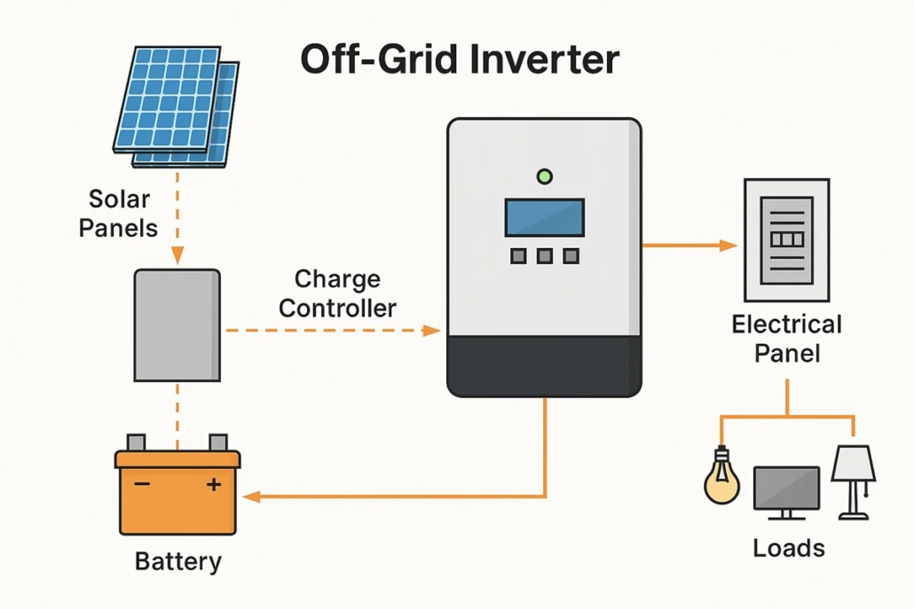
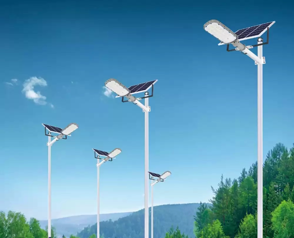
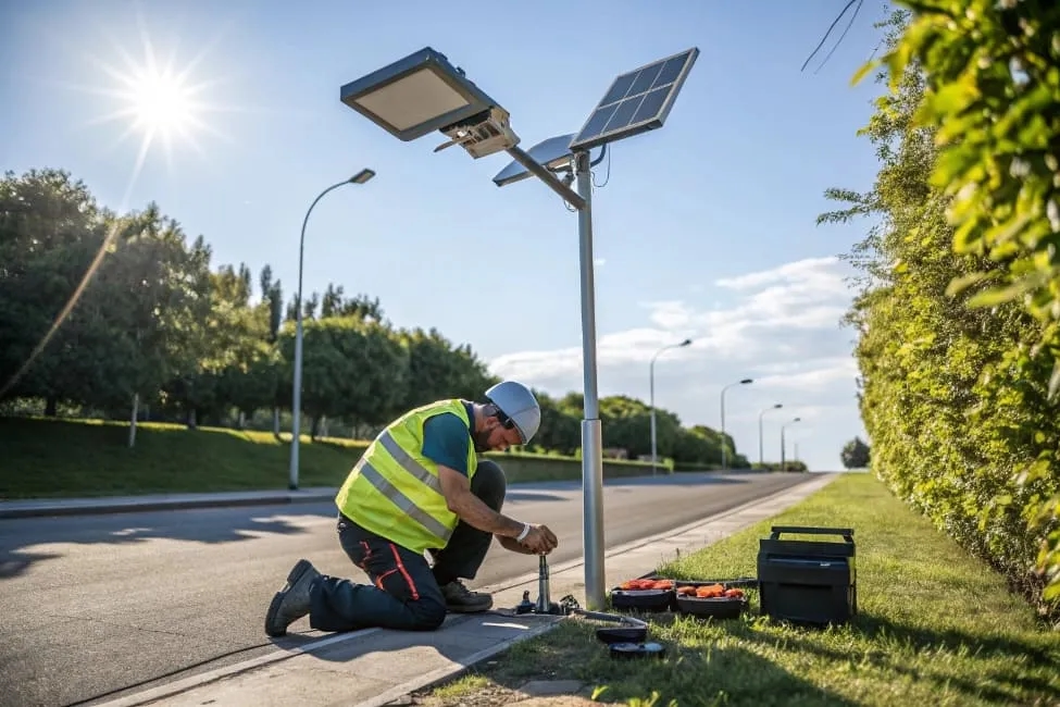
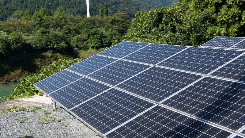
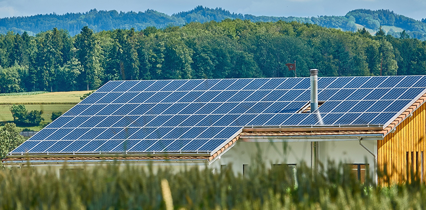
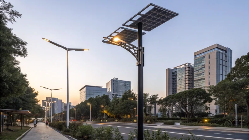
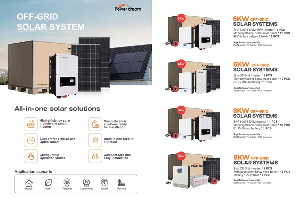
In remote areas, off-grid solar systems ensure that villages remain brightly lit at night, with rooftop solar panels and battery banks illuminating the entire community, and schools can operate without generators. This outcome depends not only on the solar panels and inverters, but also on engineers rigorously controlling the system design, assembly, and testing processes to prevent electric shock, fire, or premature failure. TÜV-certified off-grid solar systems provide this confidence through independent, repeatable testing and safety verification of components and the entire system.

The Meaning of TÜV Certification and Its Correspondence with International Standards

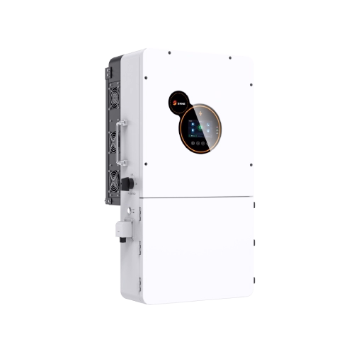
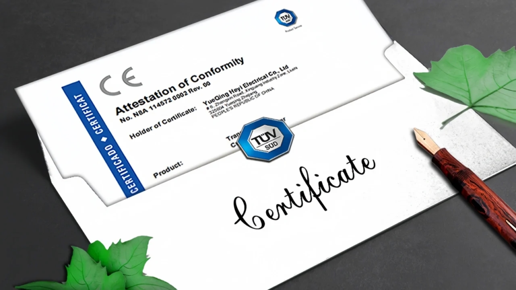
TÜV Certification is not a single testing program, but a group of globally recognized independent testing and certification service organizations. When you see the phrase “TÜV-certified off-grid solar system,” it usually means that a TÜV certification body has tested the entire off-grid solar system or its key components to confirm that they meet specific standards. There are two common certification methods: component certification (e.g., solar modules conforming to IEC 61215/61730, inverters conforming to IEC 62109, and batteries conforming to relevant standards), and system-level certification.

For example, TÜV solar kit certification verifies whether the supplied components can be safely integrated and whether the installation and documentation comply with relevant specifications. System certification typically covers electrical safety, mechanical integrity, protection rating, and completeness of documentation. Therefore, in practice, a TÜV-certified off-grid solar system indicates that a qualified testing laboratory has verified the components’ compliance and the system’s integrated safety performance, rather than just a marketing claim of “high quality.”

TÜV Certification

Technical Standards Coverage: Electrical, Mechanical, Environmental, and Functional Safety

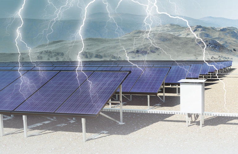
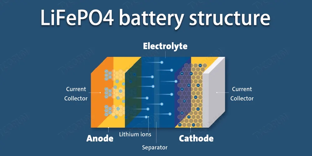
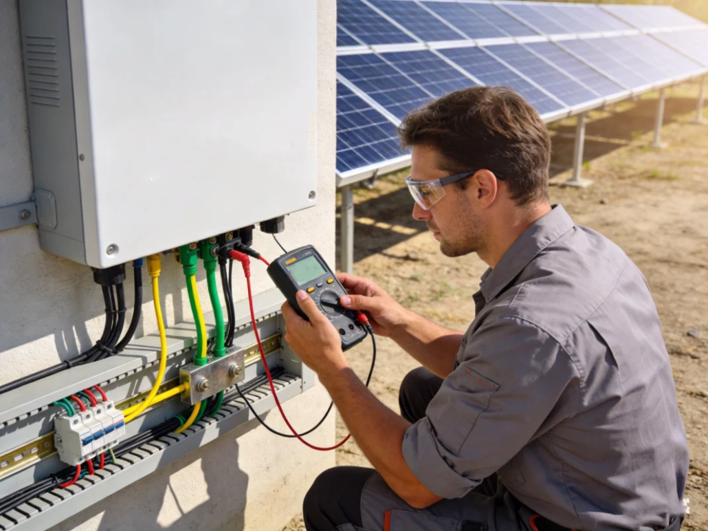
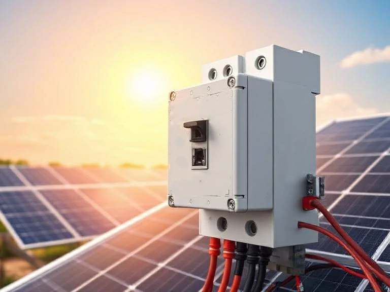
Electrical safety is paramount. TÜV audits typically assess whether off-grid solar inverters and their associated photovoltaic combiner boxes, DC circuit breakers, and AC converters comply with standards such as IEC 62109 and IEC 60364, as well as locally recognized equivalent standards. For battery storage, third-party laboratories typically conduct tests such as IEC 62619 or UL 1973 certification and perform functional safety testing on the battery management system. TÜV’s inspection includes insulation resistance, coordination of DC and AC overcurrent protection, anti-islanding/switching logic for hybrid systems, and photovoltaic reverse polarity and DC arc protection.

Since off-grid systems may include photovoltaics, inverters, batteries, and backup generators, TÜV assesses the control logic to prevent unsafe reverse feeding and ensure orderly switching—a critical safety feature in remote installations. Therefore, as long as the certificate references specific test standards and the certificate’s scope matches the deployed configuration, TÜV-certified off-grid solar systems generally meet the electrical protection requirements set by international safety standards.

TÜV-certified off-grid solar systems guarantee durability

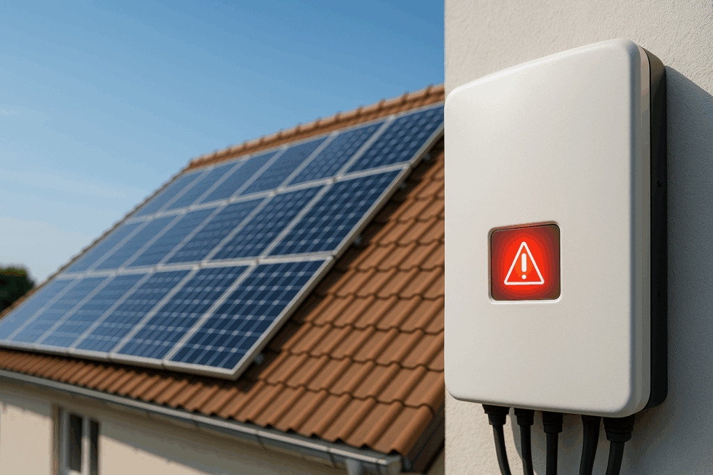
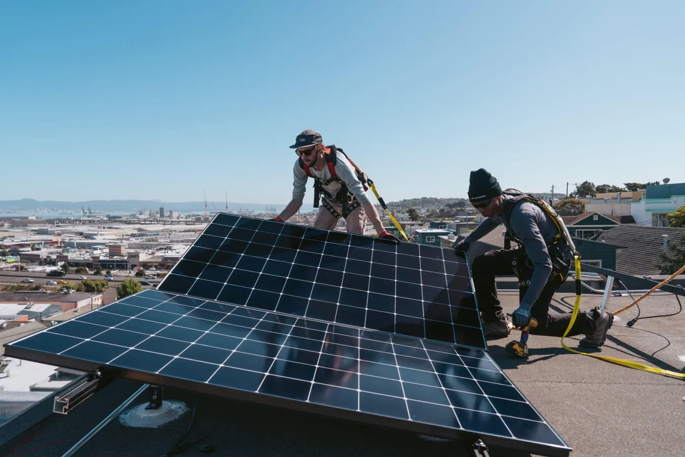
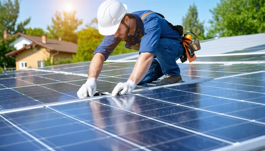
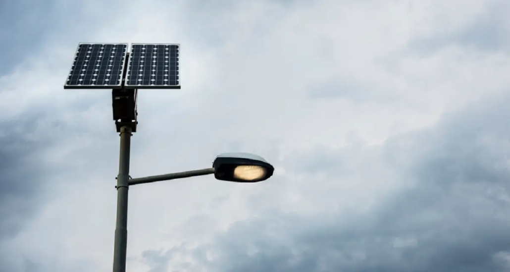
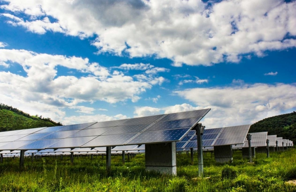
Off-grid solar systems are exposed to harsh conditions year-round, including wind, snow, dust, moisture, and extreme temperatures. TÜV certification typically includes mechanical performance assessments, such as structural calculations for pole, bracket, and component installations; wind and snow load testing; and vibration or shock testing for mobile systems. Environmental testing examines the UV resistance of polymer components, salt spray testing for coastal deployments, and the enclosure’s IP protection rating (IP54, IP65, etc.).

If a product is marked as a TÜV-certified off-grid solar system, the manufacturer must provide evidence demonstrating that the mounting hardware and enclosure can withstand local environmental conditions and that the connectors and enclosure remain safe under such conditions. This requirement is particularly important for off-grid solar systems deployed in harsh climatic environments, because seal failure or fastener corrosion can quickly lead to electrical failures. TÜV’s mechanical performance and IP protection rating tests are fully compliant with international standards, including IEC 60529 (IP protection rating) and ISO structural testing specifications.

TÜV-certified off-grid solar systems guarantee durability

System Integration and Component Interoperability of TÜV-Certified Off-Grid Solar Systems

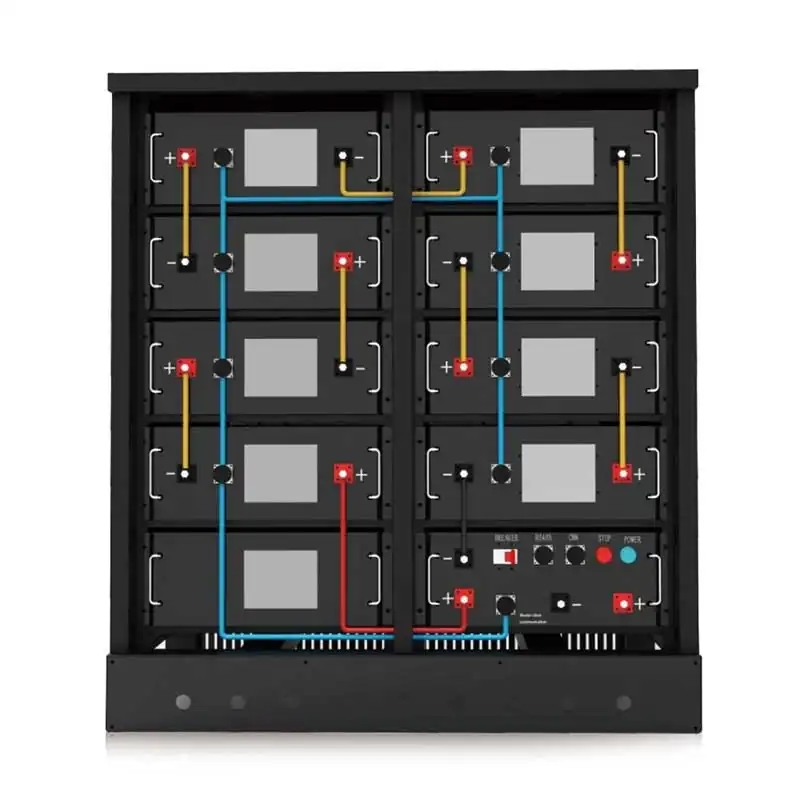
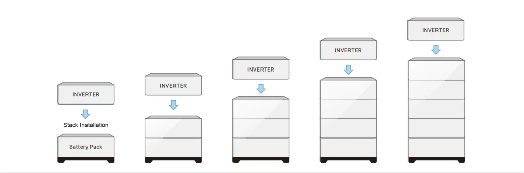
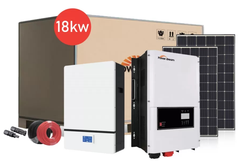
Component certification is necessary, but not sufficient. TÜV-certified off-grid solar systems emphasize integration: the interaction between photovoltaic modules, inverters, BESS, BMS, and mechanical systems. Integration testing simulates faults and confirms that the system’s protection layers can respond safely—for example, the BMS signals to stop inverter charging before overvoltage occurs, and contactor disconnection does not cause voltage spikes.

In addition, TÜV may test communication interoperability (CAN, Modbus) and the effectiveness of isolation measures. Purchasers should request a certified test plan and focus on explicit system-level testing rather than on component declarations alone. TÜV-certified off-grid solar systems with proven BMS/inverter communication scenarios reduce operational risks compared to kits loosely assembled from certified components.

Compliant with IEC, ISO, UL, NEC, and National Regulations

TÜV testing and certification bodies typically test in accordance with internationally recognized standards (e.g., IEC, ISO). They may also conduct tests compliant with national standards, such as North American UL standards or Japanese JIS standards. TÜV certificates usually list the standards referenced. For example, a TÜV-certified off-grid solar system for multiple markets may comply with IEC 61215/61730, IEC 62109, IEC 62619, and relevant grid-connected standards.

For systems installed in the United States, buyers should ensure that system components have UL certification or a TÜV certificate explicitly demonstrating compliance with UL requirements. TÜV certification can often expedite regulatory approval processes because the competent authority (AHJ) recognizes independent third-party test reports. Nevertheless, installers will still need local permits and may need to provide test reports or witness the commissioning process. TÜV certification can reduce friction in the approval process, but cannot replace local regulatory compliance requirements.

Compliant with IEC, ISO, UL, NEC, and National Regulations

TÜV Certification is the Foundation for Compliance with International Safety Standards

TÜV-certified off-grid solar systems meet or exceed international safety standards in many cases because the certification process tests all aspects, including electrical, mechanical, environmental, and functional safety, as a whole. However, certification is only one part of a safe deployment: system-level integration testing, clear commissioning and maintenance documentation, firmware management, and matching the certified configuration to your site conditions are equally important. By using TÜV-certification system kits, verifying the scope of certification, and following the supplier’s commissioning and lifecycle management processes, project owners can be confident that their off-grid solar systems will operate safely and reliably under both typical and adverse conditions.

Off grid solar inverter: Multiple Protection Features Eliminate Short Circuit/Overvoltage Risks

When a remote off grid cabin relies on solar power and a battery bank, a single wiring error or voltage spike can derail your energy plans. That’s why choosing an off grid solar inverter with comprehensive protection is crucial. PowerDream’s off-grid solar inverters feature a multi-layered safety architecture, including PV reverse polarity protection, battery overvoltage protection, overload and short-circuit protection, temperature management, surge suppression, and integration with a battery management system (BMS) to prevent minor malfunctions from escalating into catastrophic consequences.

Essential Protection Features for Off Grid Solar Inverter

The first and foremost requirement is PV reverse polarity protection. One of the most common mistakes in rooftop or ground-mounted installations is reversing the PV connector: a reversed connector can damage diodes, stress the MPPT circuitry, and cause dangerous arcing. Therefore, professional off grid solar inverters are equipped with explicit PV reverse-polarity protection, which detects DC polarity at the input and prevents current flow until the polarity is corrected. PowerDream’s off-grid solar storage inverters employ dual hardware and firmware protections: the hardware blocks DC power in the event of reverse polarity, while the inverter’s control logic reports the fault to the monitoring interface and locks the device in a safe state. Furthermore, a DC surge protector at the photovoltaic input prevents damage to the inverter from high-voltage transients such as lightning strikes or grid switching.

Essential Protection Features for Off Grid Solar Inverter

Battery Overvoltage and Undervoltage Protection Functions in Off Grid Solar Inverter

In off grid solar systems, the battery is the core of the entire device and the most sensitive component to inverter performance. An excellent off grid solar inverter must have robust battery overvoltage protection and undervoltage cutoff. If the battery is modular or a large-capacity pack, it must be integrated with an external BMS.

PowerDream’s off grid solar inverters support configurable charging cutoff voltage, absorption/float charging voltage, and SOC-based charging limits. In addition, the inverter includes a hardware relay and a fast electronic circuit breaker that trips when the battery voltage exceeds a safe threshold or when the BMS issues a critical fault signal. For lithium batteries, the inverter firmware supports temperature-compensated charging setpoints and charging current limits to prevent battery overvoltage. On the other hand, undervoltage protection prevents the inverter from operating below a safe battery voltage, thus protecting the battery from damage and extending cycle life.

Short Circuit Protection and Overload Handling Functions

Short circuits and overloads can occur in off grid systems: pump blockage, incorrect load wiring, lightning strikes, or cable faults can all cause the inverter to withstand extremely high currents. A reliable off-grid solar inverter must quickly detect short circuits and disconnect the affected output to limit fault current and prevent downstream damage. PowerDream employs multi-stage current protection: the inverter power stage is equipped with fast electronic overcurrent detection, clearing high current transients within microseconds; simultaneously, electromechanical relays or contactors trip when a fault persists. The overload protection function is adjustable and supports phased response. More importantly, the inverter logs fault events and reports fault details to a remote monitoring system, allowing technicians to diagnose the root cause without costly on-site service.

Short-circuit protection and overload handling functions for off-grid solar inverters

Advanced Protection, Environmental Protection, and System Integration for Off Grid Solar Inverter

Thermal stress is a major cause of inverter failure. Off grid inverters typically operate in harsh, un-air-conditioned environments. Therefore, professional off grid solar inverters require active thermal monitoring, conservative thermal derating profiles, and a clear enclosure design to prevent thermal runaway. PowerDream’s BHYP off-grid solar inverter provides multi-sensor temperature monitoring and implements tiered thermal protection: it slowly drains when output power exceeds a set threshold; at extreme temperatures, it reduces the MPPT’s sensitivity to limit internal heat dissipation; and it forces a shutdown if the temperature exceeds safe operating limits. Additionally, for prolonged high-temperature operation, the inverter can notify the operator and record temperature trends to support preventive maintenance.

Surge Protection and Transient Voltage Suppression

Lightning strikes and grid switching can generate transient overvoltages that can propagate into off grid systems via photovoltaic arrays, AC reverse power supplies, and even grounding systems. A robust off-grid design considers surge protection a critical feature. PowerDream integrates surge protection devices (SPDs) on both the PV DC side and the AC output/standby input side of the inverter. These SPDs are coordinated: a type 1/2 equivalent surge protector on the AC input side and a high-energy DC surge protector on the PV input side. Additionally, the inverter includes internal clamping circuitry and MOVs to absorb residual energy. Importantly, you can maintain and replace the SPD very conveniently; multiple surge events degrade its performance, so you must replace it to maintain its effectiveness.

Surge Protection and Transient Voltage Suppression in Off-Grid Solar Inverters

Choosing a Protection-First Off Grid Solar Inverter

Choosing an off grid solar inverter is not simply about selecting the kilowatt rating; it’s more about choosing a protection-first architecture to prevent wiring errors, battery damage, overheating failures, and sudden transient events. PowerDream’s off-grid solar storage inverters integrate hardware and firmware protection features, including photovoltaic reverse-polarity protection, battery over- and under-voltage handling, short-circuit and overload trip coordination, temperature protection, and surge protection. These features work together to ensure the safe and efficient operation of off-grid systems.

How can we solve the problem of the tedious and complicated installation of solar power street lights?

In many municipal and commercial projects, installing traditional grid-connected solar power street lights quickly becomes a civil engineering project, rather than a simple lighting upgrade. Traditional streetlights require trenching, laying underground cables, obtaining grid connection permits, coordinating transformers, and working with multiple subcontractors. The main challenges typically include underground cable laying, long-distance voltage-drop calculations, interference risks, and compliance checks for the power infrastructure. Trenching alone can account for 30% to 50% of the total project cost. Truly modern, simple, fast, and efficient solar streetlights should operate independently, without relying on centralized infrastructure.

The Independent Architecture of PowerDream Solar Power Street lights

Unlike traditional lighting networks, each PowerDream solar power street light is designed as an independent architecture. Each unit integrates high-efficiency solar panels, a smart MPPT controller, lithium batteries, and LED lights into a single monolithic or modular structure. Because each solar streetlight operates independently, there is no need for grid connection or underground cabling. This architecture fundamentally changes the installation process. Engineers no longer need to design centralized electrical layouts; they only need to determine the pole spacing and lighting requirements. Each solar street light can independently generate, store, and consume electricity. Therefore, there is no need for voltage balancing, transformer selection, or grid synchronization. This decentralized structure improves reliability, especially in remote infrastructure projects such as highways, industrial parks, and areas with limited maintenance access.

The Independent Architecture of PowerDream Solar Power Street lights

PowerDream Solar Power Street Lights: Trenchless Installation and Cost Optimization

Installing PowerDream solar power street lights requires only three main steps: erecting the poles, installing the solar street light fixtures, and securing the structure. No excavation, piping, or electrical cabinets are required. Because there is no need to lay underground cables, installers avoid common risks such as cable damage, water ingress, interference, or utility conflicts. This simplified installation method reduces reliance on manual labor and minimizes the use of heavy machinery. In many projects, installation time can be reduced by up to 60% compared to traditional street light systems.

Furthermore, trenchless construction significantly reduces indirect costs. No traffic diversion planning is needed in urban environments, and no environmental remediation work is required in landscaped areas. For rural and developing areas where grid expansion may be impractical or prohibitively costly, this self-contained solar street light solution is not only efficient but also crucial.

Trenchless Installation and Cost Optimization

All-in-One vs. Split-Type Solar Power Street Lights

PowerDream offers both All-in-One and split-type solar power street light configurations to meet diverse project needs. All-in-One solar power street lights combine all components—solar panels, batteries, controllers, and LED luminaires—into a compact unit, mounted directly on the pole. This design maximizes ease of installation and is ideal for rapid deployment in residential streets, sidewalks, and small commercial areas.

Split-type solar power street lights separate the solar panels and battery modules, allowing each to operate independently. This configuration offers greater flexibility in optimizing tilt angles, battery capacity, and lighting output. It is particularly advantageous for highways, ports, and industrial parks requiring higher lumen output and longer runtime. Both designs adhere to the trenchless installation concept, providing a scalable solution without sacrificing structural integrity or performance reliability.

All-in-One vs. Split-Type Solar Power Street Lights

Structural Design and Durability

Ease of installation must never come at the expense of long-term durability. Therefore, every PowerDream solar power street light utilizes a corrosion-resistant aluminum alloy structure and a reinforced pole mounting system. The lightweight yet robust design simplifies installation while ensuring structural stability under wind loads and extreme weather conditions.

Furthermore, our solar street lights feature IP-rated battery housings and sealed LED modules, protecting internal components from dust, moisture, and temperature fluctuations. The natural heat dissipation design eliminates the need for active cooling, reducing maintenance complexity and extending lifespan. Since each unit operates independently, future relocation or repositioning is also easier. If urban planning changes or road expansions occur, the solar streetlights can be safely disassembled and reinstalled without power outages.

Up to 60% Reduction in Installation Costs

From an economic perspective, ease of installation directly translates into substantial cost savings. Traditional lighting infrastructure requires excavation equipment, licensed electricians, permit fees, cable materials, and approvals for grid connections. In contrast, trenchless solar street light systems eliminate these costs. Because PowerDream solar power street lights operate independently and use renewable energy, their operating electricity costs are virtually zero. Furthermore, maintenance is much simpler due to the elimination of underground cabling.

In numerous municipal and commercial case studies, switching to All-in-One solar power street light solutions has reduced upfront installation costs by up to 60%. More importantly, predictable maintenance patterns improve budget transparency for cities and developers.

Simple and Efficient Installation

Solving the cumbersome installation process of solar street lights requires a fundamental rethinking of infrastructure. By eliminating underground cables and adopting trenchless, independently operating solar street light designs, projects can significantly reduce labor intensity, shorten construction time, and lower overall investment costs. PowerDream’s All-in-One and split-type solar street light solutions demonstrate that advanced lighting technology doesn’t necessarily mean increased complexity. Instead, when energy production, storage, and lighting are intelligently integrated into a single unit, installation becomes faster, safer, and more predictable.

Solving the problem of energy waste and increased costs caused by excessively large solar panel size

Solar panel arrays that exceed a house or site’s actual needs often lead to hidden costs, reduced operating efficiency, and energy waste. Choosing the appropriate solar panel size rather than the largest is crucial for maximizing cost savings, avoiding unnecessary system balancing costs, and improving the return on energy investment. Therefore, we will comprehensively explain why oversized solar panels lead to higher costs and energy waste, and how these issues manifest in terms of electricity, finance, and regulation.

Why do Large Solar Panel Size to energy waste and additional costs?

The problem with oversized solar panels is that their power generation capacity does not match the site’s ability to consume, store, or output that electricity. When a rooftop solar array generates more electricity than a household needs during the day, and grid-connected generation is limited or insufficient to generate a sufficient return, the system effectively wastes the excess electricity. Worse still, oversized arrays increase upfront costs, complicate system balancing, and lower the project’s overall levelized cost of energy (LCOE) if the owner cannot monetize the excess electricity.

Furthermore, several electrical mechanisms contribute to this waste: inverter limiting, output restriction, and grid connection limitations. Most residential systems use inverters selected based on the ratio of the rated power of the photovoltaic (PV) modules to the inverter’s rated power. If you significantly increase the capacity of the PV modules to reduce costs while keeping the inverter capacity small, the inverter will throttle and limit the output of the additional PV power generated during peak solar hours, which results in energy waste. If you oversize both the PV modules and the inverter, you will not only pay a higher purchase price, but you may also encounter grid connection restrictions. Therefore, an oversized monocrystalline silicon solar panel array may generate more energy than the system or applicable regulations allow.

Why do oversized solar panels lead to energy waste and additional costs

Impact of Large Solar Panel Size on Operating Costs, Structure, and Permitting

Larger solar panels mean higher system operating costs. Each additional solar panel increases the cost of mounting brackets, fasteners, labor hours, and typically requires thicker wiring and larger overcurrent protection devices. On sloping roofs, installers may require more roofing accessories, larger waterproofing layers, and more thorough structural inspections—all of which increase the complexity of approvals. Furthermore, large solar panels may change the property’s approval category or trigger utility service upgrades, increasing costs.

From a structural perspective, increasing the number of solar panels increases wind and snow loads, requiring additional engineering design or improved installation schemes. Even high-efficiency monocrystalline silicon solar panels, while generating more electricity per unit area and occupying less space, cannot eliminate the additional system maintenance and labor costs associated with large installations.

Choosing the Appropriate Solar Panel Size Based on Actual Needs

The first and most important step in choosing the size of solar panels is to conduct a rigorous load analysis. Many projects start with the available roof area or the maximum power of the panels and work backwards—this is a flawed approach. The correct approach is to quantify the household’s basic daily electricity consumption in kilowatt-hours, identify the critical loads that need to be covered, and plot hourly electricity usage patterns.

For example, if your household uses an average of 30 kilowatt-hours per day but only 12 kilowatt-hours per day in winter, and your area has unfavorable rules on electricity exports. Building a solar array capable of offsetting 100% of annual electricity consumption may not be worthwhile without an energy storage system. A practical workflow is as follows: (1) Set coverage targets; (2) Consider solar resources; (3) Consider system derating; (4) Calculate the required peak power (Wp) of the solar panels. Determining array capacity based on demand avoids building excessively large monocrystalline silicon solar panels; the usable electricity generated by these arrays may go unused or stored.

Choosing the Appropriate Solar Panel Size Based on Actual Needs

Using an Effective PV/Inverter Ratio and Clipping Analysis

A small amount of excess DC power relative to inverter capacity is beneficial because PV systems rarely operate continuously under Standard Test Conditions (STC). Many installers set the DC/AC ratio for residential systems to 1.1-1.3 to increase annual power generation while avoiding excessive clipping. However, if the DC/AC ratio exceeds approximately 1.4–1.6, clipping losses increase significantly. Use PV simulation tools to model clipping and annual power generation for a given inverter capacity, string configuration, and local irradiance conditions. These simulations can help you quantify the marginal kilowatt-hour gains and losses associated with each additional photovoltaic panel.

Equipment and Structure Selection to Reduce Losses from Large Solar Panels

High-efficiency monocrystalline solar panels deliver higher wattage per square meter, typically allowing you to achieve your energy targets with fewer modules. Fewer modules mean simpler mounting systems, fewer cables, and lower operating costs. This seemingly contradictory approach can reduce total system costs while meeting your power generation targets. Furthermore, if your goal is to match load patterns, you should plan the panel layout to avoid shading and optimize tilt/azimuth based on seasonal demand rather than maximum annual power generation.

Choosing Microinverters to Mitigate Partial Shading and Power Mismatch

If your roof geometry or shading necessitates adding more modules to reach your target capacity, consider using microinverters or power optimizers. They can reduce power-mismatch losses and enable independent module-level MPPT, ensuring each solar panel operates at its maximum efficiency even when parts of the array are shaded. While these solutions increase the cost per component, they provide higher usable energy in complex installation environments, thus reducing the temptation to over-provision.

Choosing the Right Solar Panel Size

Addressing the energy waste and increased costs caused by oversized solar panels requires careful selection based on your energy needs. A well-designed solar panel system should efficiently generate electricity that can be consumed, stored, or monetized. When system capacity exceeds actual demand or regulatory limits, additional investment often yields diminishing returns. Conversely, well-designed solar panels—especially arrays built with high-efficiency monocrystalline silicon solar panels—offer better economics, lower system balance costs, and higher long-term reliability.

Parallel expansion of 100Ah Solar Battery: Solving the problem of insufficient energy storage

In residential and small-scale commercial energy projects, energy storage capacity often becomes a bottleneck before solar power reaches its full potential. A single cell typically cannot meet the demands of peak evening demand, prolonged power outages, or off-grid applications. PowerDream addresses this limitation not by replacing the entire system, but through modular expansion. Our 100Ah solar cells feature a flexible parallel design that supports up to 10 batteries, increasing total storage capacity from 5.12kWh to 40.96kWh. This scalable architecture enables owners, installers, and project developers to address energy shortages efficiently. Furthermore, each 100Ah lithium-ion solar cell utilizes advanced lithium iron phosphate (LiFePO4) technology, combining safety, durability, and intelligent management features.

Core Technology and Expandable Architecture of the 100Ah Solar Battery

The PowerDream 100Ah solar battery uses lithium iron phosphate (LiFePO4), selected for its excellent thermal stability, long cycle life, and high safety margin. Unlike traditional lead-acid batteries, 100Ah lithium-ion solar battery maintain stable voltage output and a high usable depth of discharge, significantly improving energy efficiency.

Each module also integrates an advanced battery management system (BMS) that monitors cell voltage, temperature, and current in real time. The BMS ensures balanced charging and discharging while preventing overvoltage, undervoltage, short circuits, and overheating. This intelligent protection layer allows for safe parallel expansion without compromising system stability. The combination of high-quality cells and advanced electronic control provides a solid foundation for the modular expansion of the 100Ah solar batteries.

Core Technology and Expandable Architecture of the 100Ah Solar Battery

Parallel Expansion Capability of 100Ah Solar Batteries

A major advantage of the Power Dream 100Ah solar batteries is their ability to be connected in parallel with up to 10 cells. Each cell provides approximately 5.12kWh of nominal energy, allowing the system to expand to 40.96kWh seamlessly. This linear expansion simplifies capacity planning and avoids complex redesigns of inverters or power infrastructure. When multiple 100Ah solar cell modules are connected in parallel, the nominal voltage remains constant while the capacity increases proportionally. The built-in Battery Management System (BMS) communication function ensures synchronized operation and even current distribution across modules. Therefore, installers can progressively expand storage capacity—starting with one or two batteries and gradually increasing as household energy needs grow.

Parallel Expansion Capability of 100Ah Solar Batteries

Capacity Planning and Energy Storage Optimization

A single 100 Ah lithium-ion solar battery provides approximately 5.12 kWh of capacity. However, the usable energy depends on the depth-of-discharge setting and system efficiency. Using recommended operating parameters, users can achieve higher usable capacity while maintaining a long cycle life.

For households with insufficient energy storage, this modular approach offers flexibility. For example:

2 batteries ≈ 10.24 kWh

5 batteries ≈ 25.6 kWh

10 batteries ≈ 40.96 kWh

Furthermore, this product series supports a wide range of applications, from backup power systems to partially or fully off-grid configurations. The scalability of the 100Ah lithium-ion solar battery ensures that the energy storage system can evolve with changing electricity consumption patterns.

Installation, Durability, and Long-Term Value of the 100Ah Solar Battery

PowerDream’s 100Ah solar battery features a stacked mounting structure that maximizes space utilization. This vertical modular configuration simplifies wiring and enhances structural stability. Installers can neatly assemble the cell packs in equipment rooms or energy storage cabinets while maintaining adequate ventilation spacing. Furthermore, this lithium ion solar battery supports natural heat dissipation. Its casing design promotes air convection, reducing the need for an active cooling system. Lower operating temperatures directly translate to longer battery life and higher system reliability.

Installation, Durability, and Long-Term Value of the 100Ah Solar Battery

IP54 Protection Rating and Environmental Adaptability

Durability is crucial for home energy storage systems. This 100Ah solar battery features an IP54 protection rating, effectively preventing dust ingress and water splashes. Therefore, it is suitable for installation in garages, basements, sheltered outdoor areas, or other semi-enclosed environments.

The robust casing effectively protects internal components from moisture and environmental stressors. Combined with the inherent stability of lithium iron phosphate chemistry, this lithium-ion solar cell maintains reliable performance across a wide temperature range. These protective features reduce performance degradation caused by environmental factors and extend overall lifespan.

Safety Systems and Operational Reliability

Safety is always paramount in energy storage design. This 100Ah solar battery employs multi-layered protection mechanisms, including current limiting, temperature monitoring, and automatic shutdown protocols. An integrated battery management system ensures safe operation during charge-discharge cycles, even under fluctuating loads. Parallel expansion does not compromise safety because each lithium-ion solar battery operates independently while communicating with other modules. Even in the event of a fault, isolation mechanisms prevent the fault from spreading throughout the entire battery pack. This architecture enhances operational reliability and meets the safety requirements of modern homes.

Flexible Parallel Expansion Solves Energy Storage Shortages

The parallel expansion of the PowerDream 100Ah solar batteries addresses energy shortages in residential and small-commercial energy-storage systems. Supporting up to 10 modules in a stacked installation, they feature natural heat dissipation and an IP54 protection rating, perfectly combining electrical scalability with proven durability. This modular design reduces upfront costs, improves lifecycle economics, and allows users to flexibly expand energy storage capacity as needed, effectively addressing the challenge of insufficient energy storage to meet varying power demands.

How to Fix Grid Connection Issues in a Residential Grid-Connected Solar System?

Residential grid-connected solar system, as a stable, efficient, and economical energy source, account for the vast majority of new residential solar installations in North America and Europe. However, grid connection problems—such as inverter shutdown, zero output, voltage tripping, islanding alarms, or intermittent reconnection failures—can disrupt energy production, reduce economic efficiency, and pose reasonable safety hazards. To quickly and safely restore system performance, troubleshooting must be a structured engineering process, not a trial-and-error approach. Therefore, this guide will show you professional-grade diagnostic strategies applicable to any grid-connected solar system.

Step One—Diagnosing Grid Connection Faults in a Residential Grid-Connected Solar System

Before performing any electrical measurements or configuration adjustments, always prioritize safety. If you detect a burning smell, visible arcing, melted connectors, or repeated circuit breaker tripping, immediately turn off the switches. Before continuing, ensure that the capacitors in the inverter are fully discharged. Safety is paramount and cannot be ignored when operating residential grid-connected solar systems, as both DC and AC circuits can be energized.

For non-emergency faults, a structured rapid assessment process should be followed first. Review the inverter’s display information and historical alarm logs. Confirm that the grid is operating normally and is not under maintenance. Inspect the DC combiner box, AC circuit breaker, and disconnector. Many grid-connected solar system failures stem from loose terminals, improper torque settings, aging connectors due to weather conditions, or incorrect output configuration.

Diagnosing Grid Connection Faults in a Residential Grid-Connected Solar System

Inverter Fault Code Analysis in Residential Grid-Connected Solar System

The inverter is the central intelligent unit of a residential grid-connected solar system. It continuously monitors voltage, frequency, current, temperature, and grid synchronization parameters. Therefore, the inverter fault log provides highly specific diagnostic information that can guide corrective actions. Ignoring these fault codes may lead to repeated downtime or compliance violations. Common inverter-related grid problems include grid overvoltage or undervoltage tripping, frequency deviation, islanding protection activation, DC input imbalance, and internal overheat protection events. If the inverter reports a grid voltage exceeding permissible thresholds, measure the voltage directly at the point of common coupling (PCC) using a calibrated multimeter.

Troubleshooting DC Side Faults in Grid-Connected Solar Systems

When inverter diagnostics show low DC input voltage, string mismatch, or insulation faults, the problem is likely on the photovoltaic array side. The DC subsystem is frequently exposed to various environmental stresses, including UV radiation, temperature cycling, and moisture intrusion. These factors can cause connectors and wiring to age over time. Accurate troubleshooting of DC faults in grid-connected solar systems requires comparing real-time measurements with system design specifications. Even small deviations in string voltage can reduce inverter efficiency or prevent grid connection. By systematically testing each string, installers can isolate underperforming components and eliminate faults before they escalate.

Troubleshooting DC Side Faults in Grid-Connected Solar Systems

AC Side and Utility Interconnection Issues

Grid connection problems often originate on the AC side of the system. Because grid-connected solar systems must be precisely synchronised with the utility grid’s voltage and frequency, even small deviations can trigger protective shutdowns. Loose neutral wires, improper phase balance, or undersized wiring can all cause system instability. In such cases, the main switchboard needs to be checked to ensure that the circuit breaker ratings match the inverter output capacity. Measure line-to-line voltage and line-to-neutral voltage under load conditions. In some areas, power companies implement dynamic voltage regulation during peak solar hours, which may affect the inverter’s time to connect to the grid.

Step Two – Compliance and Safety Improvements for Residential Grid-Connected Solar System

Compliant residential grid-connected solar systems must meet local grid connection standards, such as IEEE 1547 or the regional grid specification. Anti-islanding protection ensures the inverter stops operating during a power grid outage, preventing unsafe reverse-feeding conditions. If non-compliance is found during inspection, verify that the inverter firmware matches the approved version from the power company. Update the software if necessary and confirm that the reconnection delay timer complies with regulatory requirements. In some installation environments, an external grid monitoring relay may be required.

Compliance and Safety Improvements for Residential Grid-Connected Solar Systems

Fast Shutdown and Electrical Safety Upgrades

Electrical safety regulations evolve. Many regions now require rooftop PV arrays to have fast shutdown capabilities. If your grid-connected solar system was installed before the NEC update requirements came into effect, retrofitting may be necessary. Install module-level fast shutdown devices in designated areas. Conduct simulated power outage tests to verify that the DC voltage drops within a specified time. Update warning labels and system diagrams to comply with current safety standards. These upgrades improve firefighter safety, increase inspection pass rates, and thus enhance the long-term reliability of residential grid-connected solar systems.

Restoring the Stability of Grid-Connected Systems

Troubleshooting grid connection issues in residential grid-connected solar systems requires rigorous diagnostics, a thorough understanding of relevant regulations, and precise engineering. First, conduct safety checks, analyze inverter data, isolate DC and AC faults, and verify compliance with the latest grid standards. Most grid-connected solar system failures are not due to core hardware defects but rather to misconfigurations, wiring inconsistencies, or grid instability. By applying a systematic troubleshooting approach and implementing proactive monitoring strategies, homeowners can restore seamless grid interaction.

What power ratings are most suitable for off grid home solar systems for home use?

Choosing the right power rating for off grid home solar systems requires careful consideration, quantifying daily kilowatt-hour (kWh) needs, determining system capacity based on peak load, designing battery capacity based on the required days of autonomy, selecting an inverter capable of handling surges and continuous demands, and properly matching the solar array and charge controller based on the worst-case solar irradiance months. We will guide you step by step through the trade-offs, helping you translate your household electricity habits and climate data into reliable off-grid power.

The Difference Between Power and Energy in Off Grid Home Solar Systems

A robust off grid home solar system design considers both power and energy as primary limiting factors. Power (kW) refers to the instantaneous capacity to run loads—for example, a water heater, refrigerator compressor, or induction cooktop. Energy (kWh) refers to the cumulative demand over a period of time, including the total daily electricity consumption for lighting, cooling, electronics, and HVAC systems. You need sufficient inverter power to handle peak loads and adequate battery capacity (kWh) to meet energy needs during cloudy days.

First, you need to create a household electricity inventory. List all appliances, their power ratings, and the actual daily usage time. Prioritize critical loads over non-critical loads. A typical off-grid small cabin might use 1-3 kWh per day with peak demand below 2 kW; an average family home typically uses 5-15 kWh per day with a peak load of 3-6 kW; and a fully equipped home might require 20-50 kWh or more per day with a peak load of 8-20 kW.

Why are both metrics important? Because a system with a large battery capacity but a small inverter capacity cannot power high-demand appliances, while a system with a large inverter but insufficient battery or PV module capacity will be affected by cloudy days. For a reliable off grid solar system, balancing these two metrics is crucial: the inverter capacity should be sufficient to handle peak loads with some headroom, while the battery and PV module capacity should be determined based on actual daily kWh usage and solar irradiance under specific climate conditions.

The Difference Between Power and Energy in Off-Grid Home Solar Systems

Assessing Household Electricity Consumption: Translating daily electricity usage into kWh and peak kW.

Accurate load assessment is fundamental to any off grid home solar system. The first step is a detailed power audit: measure or estimate the power consumption of lighting, cooling, water pumps, entertainment equipment, kitchen appliances, space heating/cooling, hot water supply, and chargers. Use metered data whenever possible; otherwise, refer to the equipment’s rated power and a conservative duty cycle.

To calculate daily energy consumption, multiply each device’s power by its estimated hours of use. Then, calculate the sum of the power of all loads running simultaneously during peak hours to determine the peak power. Be sure not to overlook starting currents; motors and compressors typically require 2-6 times their rated current during startup, so the inverter’s surge capacity must be sufficient to handle this. Also, consider future growth. Many households increase their electrical load over time. Providing ample inverter capacity and leaving room for expansion in the battery and PV budget can avoid costly retrofits later.

Assessing Household Electricity Consumption

Inverter Selection and System Voltage for Off Grid Home Solar Systems

The inverter is the core component of an off grid home solar system and determines which loads the home can run. When choosing an inverter, consider both its continuous power and surge power to handle the inrush current from motor starts and component startups. For small homes, an inverter with a constant power of 3-5 kW and a surge power of 6-10 kVA may be sufficient; larger homes may require a 6-12 kW inverter or a multi-inverter parallel system.

Select the appropriate system voltage based on power requirements. Low-power systems (<2–3 kW) typically use 12V or 24V, but high current at low voltage requires thicker cables, increasing losses. For typical off-grid homes beyond small cabins, 48V systems are standard because they can efficiently transmit higher power with reasonable conductor sizes.

In inverter selection, pure sine wave inverters are crucial for sensitive electronics and motors. Hybrid inverters combine the functions of an inverter and charge controller and may support AC coupling to a backup generator or grid connection for enhanced future flexibility. Also, consider the inverter’s efficiency and low-load performance. Simply put, when choosing an inverter, select a model with surge-current capability based on the expected maximum continuous load.

Solar Array Sizing Considerations

When choosing a power rating, you also need to determine the capacity of the photovoltaic array for your off grid home solar systems. This requires converting your daily electricity needs into installed peak power, while also considering site climate and system losses. The basic idea is to estimate the minimum photovoltaic power by dividing the daily required photovoltaic generation by the average peak sun hours in the worst month, and then increasing this value based on derating factors.

The rated power of the modules determines how many modules you need to install. For example, if your off-grid solar system requires 10 kWh of electricity per day, and the peak sun hours (PSH) in the worst month are 3 hours, then you need at least 3.3 kW of photovoltaic modules; after applying derating factors, you may need to install 4–5 kW of photovoltaic modules. To ensure reliability during seasonal low-light months, use conservative data from the worst month, rather than annual averages.

Pay attention to the panel orientation, tilt angle, and row spacing to avoid self-shading. East-west orientation can increase power generation in the morning and evening, but may make array installation more complex. For roofs with limited area, high-efficiency panels should be chosen to maximize power generation per unit area. Finally, match the open-circuit voltage and maximum power point voltage range of the photovoltaic cells to the MPPT charge controller and system voltage. Ensure that the MPPT controller can accept the photovoltaic array voltage under low-temperature conditions and provide the required charging current to the battery at the system voltage.

Solar Array Sizing Considerations

Battery Capacity and Power Rating

Battery capacity selection is critical to the success of many off-grid projects. For off grid home solar systems, the battery capacity must meet the set number of days of autonomous operation, i.e., the number of consecutive low-light days the system can operate without charging. Typical design targets range from 1-3 days of autonomous operation for mild climates and installations primarily for backup power, to 5-7 days or even longer for very remote residences or areas with frequent cloudy days.

The formula for calculating the required usable battery capacity is: daily critical electricity consumption × days of autonomy × safety margin. Then, select a suitable nominal battery capacity based on the allowable depth of discharge for the battery chemistry. For example, if a household needs 6 kWh of electricity per day, desires 3 days of autonomy, and uses lithium iron phosphate batteries with a 90% depth of discharge, after accounting for efficiency losses, the target nominal battery capacity would be approximately 20 kWh.

The battery’s power rating must also be considered. The battery must be able to meet the inverter’s surge current and continuous peak demand without exceeding its C-rate. In practice, parallel battery modules and a suitable BMS design can accommodate both high energy storage and high discharge power.

Choosing the Right Power Rating for a Reliable Off Grid Solar System

Selecting the optimal power rating for an off grid home solar system requires a careful balance between household energy consumption, peak load demands, and local solar resources. By accurately assessing daily kilowatt-hour needs, selecting an inverter capable of handling peak power, and designing a battery bank with sufficient autonomy, homeowners can achieve reliable, sustainable off-grid power. Appropriate solar array sizing, panel orientation, and hybrid charging strategies can further enhance system resilience, ensuring a continuous power supply to the home even during cloudy days.

How does Power Dream’s hybrid inverters maximize solar energy utilization with an MPPT efficiency of 99%?

In such a dynamic environment, every watt of electricity generated by a photovoltaic array is crucial. Power Dream’s hybrid inverters precisely capture this fleeting power and convert it into usable energy, thanks primarily to the industry-leading 99% efficiency of its MPPT subsystem. We will explain, from a practical engineering perspective, how our hybrid inverters and system-level design solutions maximize solar energy utilization and are suitable for various deployment models—from small residential hybrid solar power systems to large commercial grid-connected hybrid inverter arrays.

The Importance of 99% MPPT Efficiency for Hybrid Inverters

Maximum Power Point Tracking (MPPT) is the core algorithm of any hybrid inverter in a hybrid solar power system. MPPT continuously adjusts the electrical operating point of the photovoltaic array, enabling the panel to produce the maximum possible power under given instantaneous irradiance and temperature conditions. Overall, a 1-2% difference in MPPT efficiency translates into a significant amount of extra energy gained annually, and 99% MPPT efficiency transforms this slight difference into an important, measurable benefit.

First, the 99% efficient MPPT captures almost all extractable power, even under rapidly changing irradiance conditions, by narrowing the search step, reducing conversion jitter, and quickly converging to the actual maximum power point.

Second, in hybrid solar power systems utilizing battery storage, 99% MPPT efficiency improves the charging acceptance rate. The battery’s charging acceptance rate depends on its state of charge (SOC): when the SOC is low, the battery can accept higher charging power; when the SOC is high, the charging acceptance rate decreases.

Third, the 99% MPPT subsystem can reduce the overall levelized cost of electricity (LCOE) by increasing the amount of electricity generated over its lifespan without changing the installed PV capacity. This is especially important for systems with limited roof space, high component costs, or limitations on additional PV installations. Finally, MPPT efficiency interacts with other advanced features, such as dynamic maximum power point tracking under partial shading, multi-string or multi-MPPT topologies, and machine-learning-assisted irradiance change prediction, thereby further increasing power generation.

The Importance of 99% MPPT Efficiency for Hybrid Inverters

How does Power Dream’s hybrid inverters design support maximum energy harvesting?

Power Dream’s hybrid inverter architecture is optimized end-to-end: the front-end PV capture, MPPT stage, DC bus management, and inverter output stage work together to achieve highly efficient energy transfer. Three key architectural pillars enable this: multi-MPPT segmentation, high-resolution sensing and control, and advanced DC link management.

Multi-MPPT Segmentation: In commercial and residential hybrid solar power systems, string mismatch and partial shading can cause different strings to exhibit different I-V curves under the same irradiance. Power Dream implements multiple MPPT channels, each tracking with near single-module resolution. Each MPPT channel runs its own algorithm, achieving up to 99% efficiency, so shaded strings do not drag down the entire array’s performance.

High-Resolution Sensing and Control: To achieve 99% MPPT efficiency, the hybrid inverter must sample PV voltage and current with high precision and high sampling rate. Power Dream employs high-bandwidth analog-to-digital converters (ADCs), a compact analog front-end design, and digitally compensated measurement paths to reduce noise and measurement errors.

DC Bus and Power Stage Optimization: Power Dream’s hybrid inverter utilizes a low-loss DC bus topology, minimizing the number of DC-DC conversions.

Finally, firmware-level energy orchestration seamlessly coordinates MPPT output, battery charging setpoints, and load prioritization. Power Dream’s optimization strategy maximizes on-site PV utilization while ensuring battery protection and safety.

Supports maximum solar energy harvesting

Energy Savings, Extended Lifespan, and Grid Services Support

Hybrid solar power systems rely on batteries to convert intermittent PV generation into continuous power. Power Dream’s hybrid inverter precisely manages battery charging, achieving 99% maximum power point tracking (MPPT) energy harvesting without compromising battery lifespan.

Charging Accuracy: With high MPPT efficiency, the inverter can deliver more energy to the battery faster. However, batteries have limited capacity and require specific charging curves and temperature-compensated voltages. Power Dream’s hybrid inverter supports programmable charging curves and fast constant-current charging, intelligently adjusting charging rates as PV power increases. This ensures that the extra energy gained from 99% MPPT efficiency does not force the adoption of aggressive charging modes, thus avoiding shortening battery life.

Thermal-Aware Charging and BMS Integration: Batteries perform optimally within specific temperature ranges. The hybrid inverter monitors battery temperature by communicating with the BMS and adjusts charging voltage and current accordingly. If high MPPT energy harvesting coincides with high battery temperatures, the inverter reduces the charging rate to avoid thermal stress while prioritizing critical load demands.

Intelligent SOC and Peak Shaving Strategies: Power Dream’s hybrid inverters employ predictive SOC management to optimize both self-consumption and grid-connected performance. In off-grid hybrid solar power systems, the inverter prioritizes maintaining the reserve SOC required to meet peak nighttime electricity demand. For grid-connected hybrid inverter systems with grid output capability, the inverter can flexibly output surplus energy while maintaining a minimum battery reserve.

Furthermore, the hybrid inverter’s fast response capabilities enable it to act as a dynamic buffer during transient changes in cloud cover, smoothing photovoltaic power delivery to connected loads and reducing battery cycling stress.

Energy Savings, Extended Lifespan, and Grid Services Support

MPPT Tracking Algorithms, Prediction, and Adaptive Control for Solar Utilization

High MPPT efficiency is necessary, but not sufficient. Power Dream’s hybrid inverters employ multi-layered adaptive algorithms and predictive models to translate MPPT gains into continuous system-level optimization. These features include intelligent ramp detection, integration of irradiance prediction, and load prioritization heuristics.

Intelligent Ramp Detection and Dynamic Step Size Control: MPPT search strategies must be fast enough to capture transient irradiance peaks while being stable enough to avoid oscillatory behavior. Power Dream’s MPPT uses dynamic step-size control, increasing search intensity during rapid irradiance increases and decreasing it during steady-state conditions to prevent overshoot. This approach improves capture rates during ramp events and prevents reduced MPPT efficiency due to micro-oscillations.

Prediction-Based MPPT and Charging Planning: By integrating short-term irradiance forecasts, the hybrid inverter can proactively plan the battery charging and discharging sequence. If the system predicts stormy weather, it can maintain a higher state of charge (SOC) to cope with cloudy conditions; if it predicts a sunny afternoon, it can release more power in advance to increase daytime load compensation.

Load-aware MPPT allocation: In a hybrid solar power system with critical and optional loads, the inverter dynamically allocates harvested energy according to priority. For example, when photovoltaic power generation reaches its maximum, the hybrid inverter will prioritize powering immediate loads and charging the battery, and only after these loads are satisfied will it begin to output optional power.

Maximizing solar energy utilization into tangible value

Power Dream’s hybrid inverters are meticulously designed to capture, manage, and convert virtually every watt of solar energy into tangible value, boasting an industry-leading MPPT efficiency of up to 99%. By combining advanced multi-MPPT architecture, intelligent system-level control, seamless battery integration, and robust thermal and reliability design, each hybrid inverter becomes the core intelligent control unit of a high-performance hybrid solar power system. This comprehensive approach not only maximizes solar energy utilization under varying weather and load conditions but also extends battery life and reduces reliance on the grid.

How does Power Dream provide solar street lighting solutions tailored to different situations?

When providing solutions for each customer requiring solar street lights, we meet specific needs by translating site-specific data into engineering solutions. Our solar street lighting solutions combine the following aspects: precise determination of solar panel tilt and azimuth angles, meteorological resource analysis, precise load curve analysis for solar street light fixtures, and battery capacity design that fully considers continuous cloudy days and extreme low-temperature derating. We offer customized solutions, from photovoltaic arrays to LED luminaires, from MPPT charge controllers to lithium iron phosphate battery packs and cloud monitoring, ensuring your lighting needs are met.

Latitude, longitude, and local meteorological resources determine the design of solar street lighting solutions

For each solar street lighting solution, Power Dream first collects the site’s latitude and longitude and extracts local meteorological data: monthly average solar radiation (insolation), average temperature range, typical wind speed, annual rainfall/snowfall patterns, and the historical number of consecutive low-insolation days. These parameters determine the expected solar resources and various environmental factors affecting photovoltaic output, battery capacity, and mechanical design.

Why use latitude and longitude? Because the sun’s trajectory, altitude angle, and azimuth angle directly depend on geographical coordinates. Using these coordinates, we can determine the sun’s seasonal angle and calculate the optimal tilt and azimuth angles for the photovoltaic array to maximize annual or seasonal solar energy capture. For example, in the Northern Hemisphere, we typically orient the array towards due south (an azimuth angle of approximately 180°). In contrast, in the Southern Hemisphere, we orient it towards due north (an azimuth angle of roughly 0°). Near the equator, sensitivity to the azimuth angle decreases, and other factors, such as shading and obstructions, become more significant.

Latitude, longitude, and local meteorological resources determine the design of solar street light solutions.

Determining Solar Street Lighting Solutions Based on Optimal Tilt and Azimuth Angles

Optimizing the tilt and azimuth angles of the solar panels for solar street lights balances annual power generation, seasonal performance, and snow or dust removal. Here’s how Power Dream determines the optimal tilt and azimuth angles:

Azimuth Angle: Target due south (180°) in the Northern Hemisphere and due north (0°) in the Southern Hemisphere; if the operational goal is to improve visibility during early morning and late evening hours, a slight eastward/westward deviation may be considered. For roads with heavy traffic at night, a slightly westward azimuth angle may be more advantageous for nighttime visibility.

  • Tilt Angle: To obtain maximum annual energy, we set the tilt angle approximately equal to the site latitude ± a specific application adjustment value:
  • Latitude as tilt angle ≈ is a good baseline for year-round production.
  • Latitude + 10–15° ≈ is favorable for winter energy (valuable in cold, short-day areas at high latitudes).
  • Latitude − 10–15° ≈ favorable for summer energy (suitable for areas where summer demand is dominant).

Tilt to facilitate snow shedding: In areas with snowfall, we increase the tilt angle to promote snow shedding and minimize snow coverage on the panels.

Adjustable tilt angle: For some large or critical installation projects, we design brackets with adjustable tilt angles that can be changed seasonally. While this design is uncommon in single-pole solar street light installations, it is attractive for municipal or campus pilot projects.

Daily Power Consumption and Charging Requirements Based on Lighting Duration

Power Dream first determines the daily energy consumption requirements of a single solar street light based on the LED luminaire’s rated power, the actual lighting duration, and the drive system’s energy consumption losses. If the project uses dimming or sensor control strategies, we comprehensively evaluate the power ratio across different operating periods rather than simply applying the full-power condition.

Based on this, we further consider the battery charge and discharge efficiency, the controller’s energy conversion efficiency, and the actual output attenuation of the photovoltaic modules under high-temperature, dusty, and installation-angle conditions to determine the effective charging energy required by the system under normal operating conditions. By combining daily energy consumption requirements with the average daily sunshine conditions of the least favorable month in the local area, we can accurately determine the charging capacity required by the solar panel under limited-sun conditions, ensuring that the solar street lights can maintain stable operation even on cloudy or low-light days.

Daily Power Consumption and Charging Requirements Based on Lighting Duration

Battery Capacity Configuration Based on the Number of Consecutive Rainy Days

The battery system is the core of the entire solar solution’s risk resistance. When designing the battery capacity, Power Dream explicitly considers the independent operation capability of the solar street lights under continuous rainy or low-irradiance weather conditions. We first determine the number of days the system needs to operate without effective charging, based on the stable daily power consumption of a single solar street light. This “consecutive cloudy days” indicator is typically set based on local long-term meteorological data and the project’s importance. Subsequently, we safely increase the battery capacity, considering the recommended discharge depth and cycle-life characteristics of the selected battery type, to avoid frequent deep discharges that could shorten battery life.

Furthermore, the impact of ambient temperature on battery usable capacity is also included in the design considerations. In cold regions, low temperatures can reduce adequate capacity, so we reserve space for temperature compensation during the capacity selection phase. Through this multi-layered capacity assessment method, Power Dream ensures your solar street lights maintain reliable illumination even on consecutive days without direct sunlight.

Lighting of solar-powered streetlights on cloudy days.

Solar Panel Power Configuration and Power Recovery Capability Assessment

After completing the battery capacity design, Power Dream further verifies whether the installed solar panel power in the solar solution can quickly recover power. Our design goal is not only to “maintain operation,” but more importantly, to restore the battery to a safe power level within a reasonable time after cloudy weather ends.

Therefore, we comprehensively consider the total energy consumption during consecutive cloudy days and set an acceptable power recovery period. Based on this, the solar panel power configuration must meet two conditions: first, to cover the daily lighting power needs of the solar street light, and second, to replenish the previously consumed energy storage within a limited number of daylight hours.

By combining effective daylight data from the least favorable months and the overall system energy conversion efficiency, we can determine the required solar panel power level for each solar street light. At the same time, Power Dream verifies that the solar panel’s working voltage and current range closely match those of the MPPT controller and battery system, ensuring efficient charging even under low-light and cloudy conditions.

Energy Consumption Optimization and Operating Strategies in Different Application Scenarios

In different application scenarios, solar street lighting solutions do not rely solely on simply increasing hardware parameters, but rather on system-level optimization to reduce energy consumption and improve overall reliability. For example, on rural roads or in park settings with low traffic volume, Power Dream typically uses time-based dimming or motion-sensing strategies to reduce average nighttime energy consumption, thereby indirectly extending battery life. This operating strategy effectively reduces the rigid requirements for solar panels and battery capacity without compromising basic lighting safety, thereby increasing the system’s adaptability in cloudy and rainy weather.

By combining intelligent control logic with a reasonable hardware configuration, the solar streetlights can operate stably under complex environmental conditions while balancing cost control and long-term reliability.

Bringing you reliable and efficient solar street lighting solutions

When providing solar street lighting solutions to our clients, Power Dream analyzes latitude, longitude, solar radiation resources, temperature, wind distribution, and historical rainfall patterns. We customize each solar street lighting system to match the specific installation scenario perfectly. From optimizing the tilt angle and azimuth of the solar panels to precisely matching daily energy consumption, battery life, and post-rain recovery, every design decision serves one purpose: to ensure stable, long-term lighting for our customers while minimizing maintenance and maximizing energy efficiency.

Power Dream off grid PV solution: “All-in-One” Residential PV Systems

A truly plug-and-play residential energy system, which a certified installer can connect to the main distribution box in less than a day—drawing clean DC power from rooftop PV modules, which the inverter seamlessly converts to AC and intelligently controls—can power the house, charge the battery, or feed surplus power back to the grid. This is the off grid PV solution offered by PowerDream. Furthermore, the off grid solar system designed in this solution is TÜV Solar Kit certified, globally compatible, simplifies installation, and maximizes self-consumption. It is ideal for residential use and delivered ready to use, adaptable to any roof or grid.

PowerDream Off Grid PV Solution: Integrated Plug-and-Play Design

PowerDream’s off grid PV system features a fully integrated design: PV modules, MPPT charge controllers, hybrid inverters/chargers, battery interface, AC distribution interface, and communication telemetry equipment are all pre-matched and tested in the factory. Our products are unique in their “integrated” solution: installers don’t need to procure various components and perform complex system matching on-site; instead, they receive the system directly from a pre-wired modular rack or compact chassis. For off-grid residential users, this reduces commissioning time and grid connection errors.

We equip each off grid solar system with an integrated hybrid inverter that performs four functions simultaneously: directly harvesting MPPT energy from the PV array, DC-DC regulation of the battery pack, converting inverter output current to household AC bus current, and providing an optional bidirectional AC interface for easy grid connection of output or input power. This hybrid inverter can operate in multiple modes, ultimately forming a compact, robust off grid solar system.

PowerDream Off-Grid PV Solution

Why is integration important for installers and homeowners?

Integration offers numerous practical advantages: consistent electrical characteristics (open-circuit voltage/maximum power voltage, cable size, connector specifications), standardized mechanical mounting interfaces, pre-configured battery management system/inverter communication, and TÜV Solar Kit certification. Therefore, installers can reduce on-site configuration time and focus more on safe and compliant installation.

Electrical Compatibility: Supports 230V and 120/240V Residential Systems

PowerDream’s global off grid PV solutions support the most common residential voltages. A hybrid inverter delivers 230V single-phase output or 120/240V split-phase output, and installers can select the configuration during commissioning or through the onboard software. The inverter’s AC output stage uses electrical isolation and complies with national grid standards when users require grid connection. For purely off-grid installations, the inverter generates the reference voltage and frequency for the home.

The system’s AC connection design is simplified for ease of installation: the hybrid inverter connects to a dedicated sub-distribution panel or main distribution box via a clearly labeled, lockable circuit breaker. Installers can select a “critical load” sub-distribution panel to prioritize circuit protection, allowing users to protect critical loads without rewiring.

Flexibility in Mechanical Structure and Installation Location

PowerDream’s off grid solar system utilizes all-aluminum solar brackets and corrosion-resistant hardware, designed for long-term outdoor use. Installers can use these brackets for most roof types—tile roofs, metal roofs, asphalt shingle roofs, and low-slope waterproof roll roofs—and they can also use them for ground-mounted systems when roof access is limited. The bracket design balances lightweight, high strength, and thermal expansion characteristics, ensuring the module array remains aligned during thermal cycling. The off grid PV solution also includes a pre-packaged set of anchor points, waterproofing membranes, and tilt adjustment options, allowing installers to achieve optimal panel azimuth and tilt angles with a single site survey.

Flexibility in Mechanical Structure and Installation Location

Operating Modes of PowerDream Off Grid PV Solutions

PowerDream’s off grid PV systems are equipped with an intelligent energy management system that dynamically switches between solar power, batteries, and optional grid resources. Users can choose different operating modes: maximize self-consumption, battery priority, or grid-assisted. Hybrid inverters support automatic switching, so during grid outages, if the system is already connected to the grid, the inverter automatically isolates the system and seamlessly uses batteries and solar power to supply critical loads without requiring user intervention. This intelligent switching feature protects equipment and enhances the user experience. For example, in solar-first mode, when solar power generation meets load demand, the system reduces grid load to almost zero; in outage mode, the inverter connects to the grid to prevent power feedback.

Operating Modes of PowerDream Off-Grid PV Solutions 1

Upgradeability and Modular Scalability

A significant advantage of the PowerDream off grid solar solution is its modular upgrade capability. Owners can first build a basic system that meets critical load requirements, and then add solar modules, battery modules, or even higher-power inverters as budget or demand increases. Because all systems are based on standardized communication buses and modular mechanical interfaces, expansion is very convenient. This modular off-grid solar system design also simplifies the replacement process. When the battery pack reaches the end of its life, technicians can replace individual modules instead of replacing the entire system.

TÜV Solar Kit Certification and PPP 59061A Compliance

All PowerDream off grid PV systems are TÜV Solar Kit Certified and PPP 59061A compliant, indicating that these systems meet third-party requirements for components, labeling, and safe installation. TÜV certification covers key areas: electrical safety, mechanical integrity, and documentation integrity. PPP 59061A compliance assures relevant regulatory bodies and standard setters that the off-grid PV solution meets modern safety and performance requirements.

The Best Solution for Off Grid Users

PowerDream’s off-grid PV solutions address the practical needs of installers, the reliability expectations of homeowners, and the explicit requirements of regulatory bodies. The “integrated” design reduces commissioning time and ensures factory-proven component compatibility. Whether your goal is to enhance outage resilience, increase energy self-consumption, or achieve partial grid independence with grid-connection capability, these systems provide a flexible platform supporting 230V and 120/240V applications and can operate anywhere in the world.