Hybrid solar power system: Smart Solar/Battery/Grid Switching Solves Grid Outage Power Blackouts
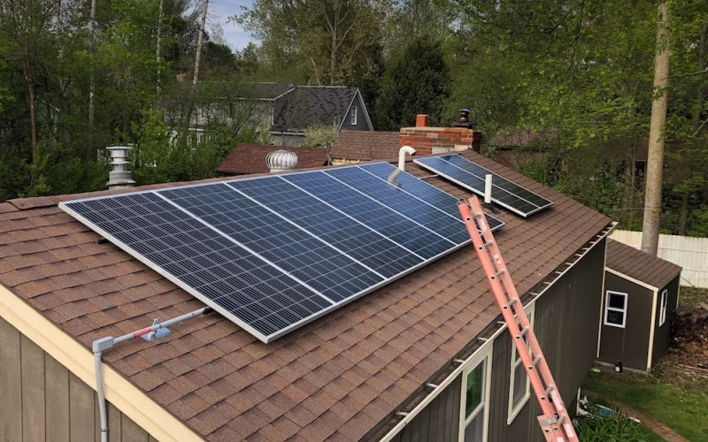
A power outage lasting several hours can be dangerous for people who rely on medical equipment. However, if a home or facility can detect a power outage, immediately disconnect from the grid, and continue to power critical loads using a rooftop photovoltaic system and battery bank—seamlessly and safely—with power restored within minutes once sunlight returns, this capability is the advantage of a well-designed hybrid solar power system. Power Dream’s intelligent hybrid solar power system demonstrates how it switches between solar, battery, and grid power to prevent outages and maximize system resilience.
Design and Control Principles of Hybrid Solar Power System
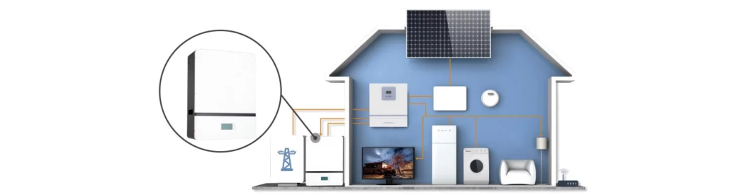
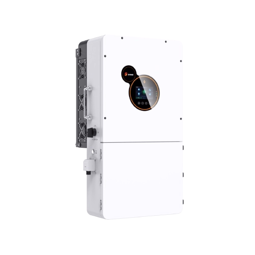
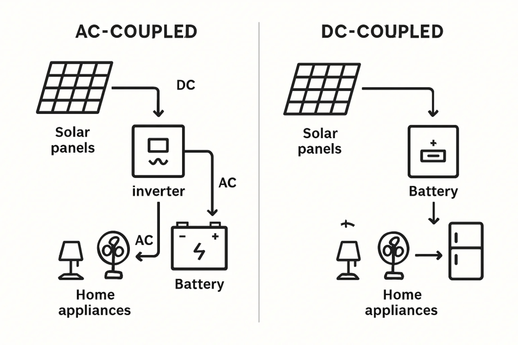
The Power Dream hybrid solar power system combines photovoltaic power generation, a battery energy storage system, a hybrid inverter, and an intelligent control layer to manage energy flow between solar panels, batteries, the grid, and loads. Unlike grid-tied or off-grid solar systems, hybrid solar power systems can dynamically switch operating modes: when the grid is available, the system operates in grid-tied mode; during grid outages, the system switches to island mode to maintain power to critical loads using batteries and photovoltaic power. The advantage lies in continuity: the system prioritizes solar self-consumption, charging the batteries via an MPPT charge controller, and automatically enabling grid or generator backup power only when needed. The integration of these functions enables features such as peak shaving, time-of-use optimization, and demand response, while also providing reliable emergency power.

Intelligent Switching Mechanism: Automatic Switching and Seamless Inverters
The core of preventing power outages lies in the switching mechanism, which isolates the user’s premises from the faulty grid and safely reconnects them after the system resolves the fault.
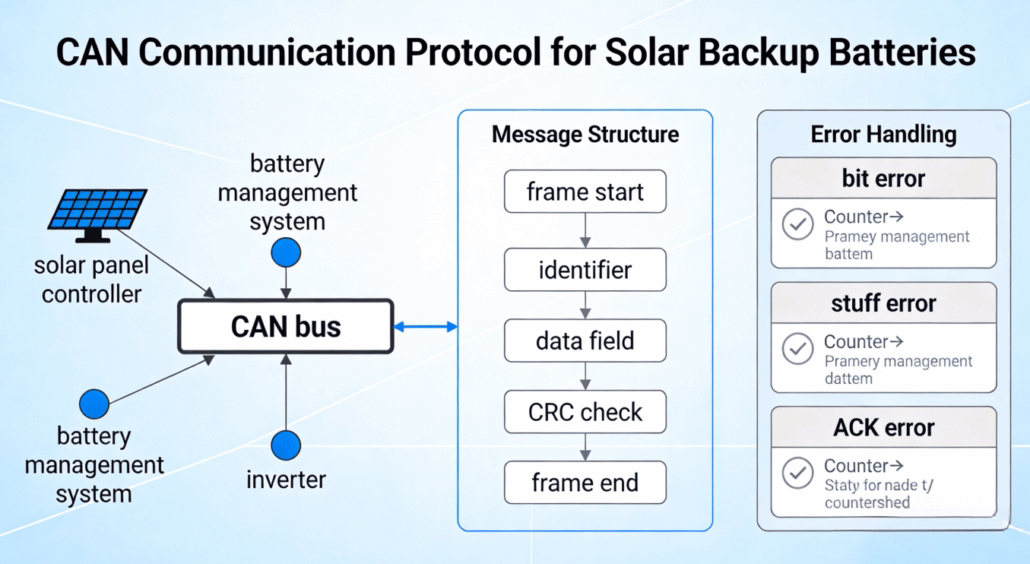
Hybrid solar systems primarily use two methods: (1) a seamless hybrid inverter with built-in islanding capabilities that switches power sources within sub-cycle to cycle times; (2) an automatic transfer switch (ATS) used in conjunction with traditional inverters and generator systems for controlled switching. Seamless hybrid inverters can detect grid faults, disconnect the grid relay, and immediately draw power from batteries and solar power with minimal impact on most loads, minimizing downtime for sensitive electronic equipment. On the other hand, this solution coordinates the inverter, generator, and load panel through set switching times, and engineers typically use it in large commercial hybrid systems or retrofit projects. Both methods require robust synchronization logic and anti-islanding protection to meet safety standards.
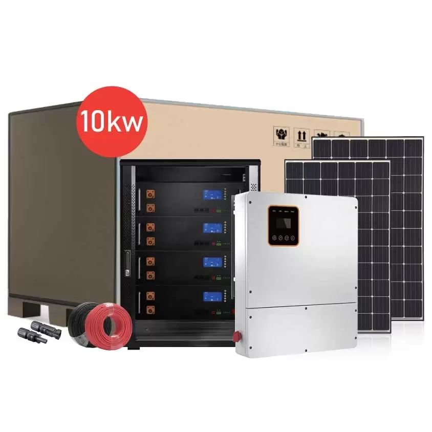
Key Components of a Hybrid Solar Power System
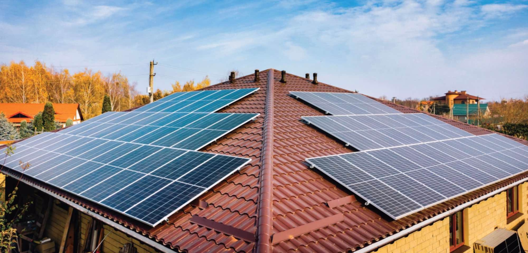
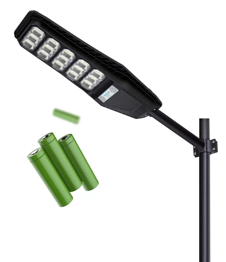
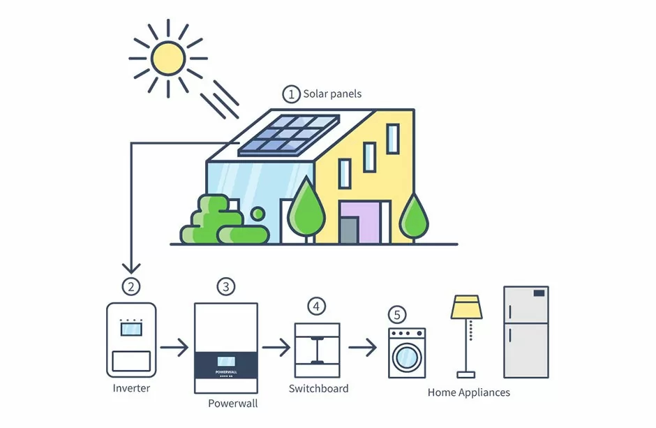
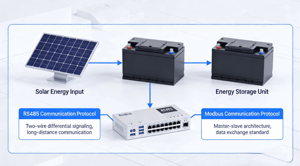
A practical hybrid solar power system consists of five basic systems. First, the photovoltaic array capacity must be selected based on daily electricity demand and the charging window. Second is the battery bank, where the usable capacity and discharge rate must be clearly defined. Third is the hybrid inverter/charger, which is responsible for DC-AC conversion, MPPT control, and islanding operations. Fourth is the automatic transfer switch, or static switch, which safely disconnects and reconnects to the grid. Fifth is the control and communication module, responsible for coordinating when to charge, discharge, shed load, or start the generator. Engineers must match each component: the inverter’s continuous and surge power ratings must meet peak load demands; the battery’s nominal voltage must match the inverter’s bus architecture; and the photovoltaic cells’ open-circuit voltage and short-circuit current must meet maximum power point tracking and safety margin requirements.
How to Determine the Capacity of PV, Batteries, and Inverters for Reliable Power Outage Performance?
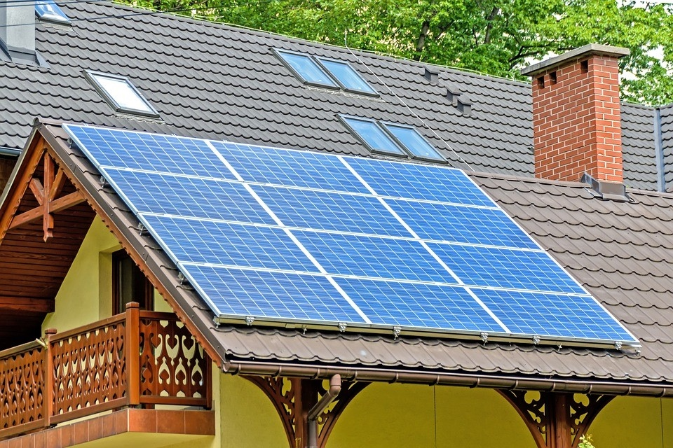
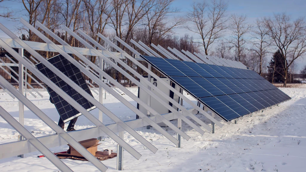
A hybrid solar power system that truly prevents power outages depends on proper capacity sizing. Our engineers conduct a load survey to determine the kilowattage and daily energy consumption of critical loads. Based on this, they design the battery capacity to provide the required autonomy time and select an inverter with sufficient continuous and surge power to handle motor starting and peak demands. Engineers size the PV array capacity to balance charging time and available roof area based on the peak sunshine hours of the worst month, ensuring that the batteries can be fully charged within the target time. The design often includes a higher PV power/peak power ratio or multiple MPPT strings to maximize charging efficiency under low irradiance conditions.
Operating Modes: Grid-Tied, Grid-Following, Grid-Connected Generation, and Emergency Power Supply
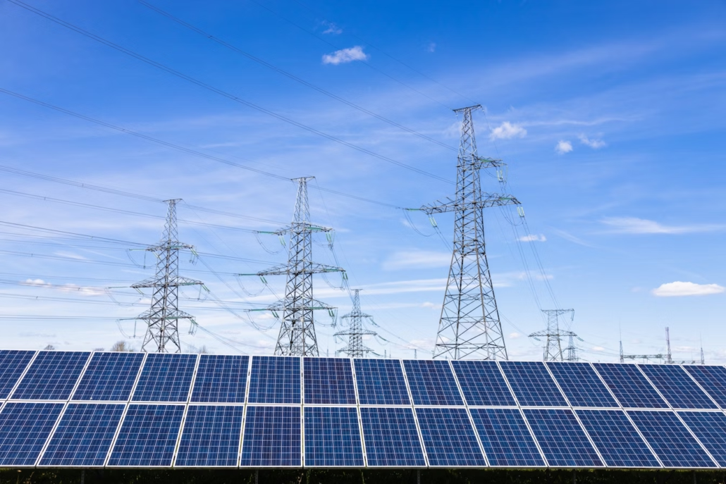
Hybrid solar power systems support multiple operating modes. In grid-tied/grid-following mode, the inverter synchronizes with the grid voltage and frequency and often outputs surplus power. Grid-tied mode is crucial during power outages: the inverter establishes an AC reference voltage and maintains a stable voltage/frequency to ensure regular load operation. Emergency power mode isolates and powers critical load panels; some systems combine grid-tied inverters with controlled load management to extend runtime. Hybrid inverters that rapidly switch between grid-tied and grid-following modes offer superior reliability, enabling the system to operate in a microgrid configuration when needed.
Addressing Power Outages
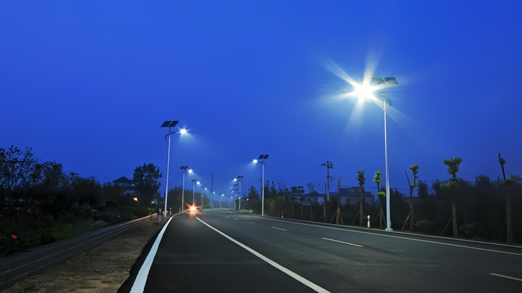
A well-designed hybrid solar system not only provides temporary lighting during power outages but also enhances energy reliability during critical moments. Intelligent solar/battery/grid switching, combined with the right hybrid inverter, automatic transfer switch logic, and control algorithms, effectively prevents power outages from escalating into catastrophic events. Power Dream level hybrid solar power systems provide reliable, economical, and compliant power outage protection by prioritizing critical loads, implementing safe anti-islanding measures, intelligently integrating generator support, and offering robust monitoring and maintenance.