Grid Compliance Checklist for On Grid Solar System
When purchasing or operating an on grid solar system, it’s crucial to ensure compliance with grid codes, safety standards, and utility interconnection regulations, as they form the legal and operational basis for your system’s ability to connect to the power grid, export electricity, and maintain connectivity. Grid compliance protects personnel, safeguards revenue, prevents cascading blackouts, and ensures predictable system behavior during grid events such as frequency excursions, voltage sags, and islanding.
Standards, Certifications, and the Regulatory Environment On Grid Solar Systems Must Verify
Grid compliance begins with standards. When evaluating any on grid solar system, ask the manufacturer or supplier to submit evidence of compliance with your jurisdiction’s key technical standards and global type tests. In the United States, key reference standards include IEEE 1547 for interconnection and performance, as well as UL 1741 for inverter safety. For Europe and many global markets, EN 62116, EN 50549 / EN 50438, as well as IEC 61727, apply to the interconnection of utility-scale and distributed generation. Systems often require compliance with electromagnetic compatibility (EMC) standards, such as the IEC 61000 series, and they also require verification of anti-islanding effects.
Checklist for procurement:
1. PV inverter type test certificates (UL 1741, IEC 62109), including documented results of performance during anti-islanding effects, harmonics, and voltage and frequency deviations.
2. Grid code compliance declaration relevant to the target utility: including IEEE 1547, local grid codes, and any local technical requirements.
3. Harmonic and EMC reports showing total harmonic distortion (THD) levels and compliance with their limits.
4. Safety certifications (e.g., CE marking, CB Scheme certification) and documentation for electrical safety components.
5. Environmental and component standards, including IP ratings (IP65/IP66) for outdoor equipment, surge protector (SPD) ratings, and material compliance.

Anti-Islanding, Fault Ride-Through, and Dynamic Grid Support
Anti-islanding and fault ride-through behavior are core features that determine a solar power plant’s ability to maintain connectivity during grid abnormalities. When purchasing a on grid solar system, verify its functional behavior and confirm the configurable parameter ranges.
Anti-Islanding: For safety and power quality reasons, utilities prohibit uncontrolled islanding. Therefore, on grid solar system suppliers are required to provide evidence of islanding resistance, including type test results in accordance with IEC 62116 or equivalent standards, as well as the specific test methods used.
Fault Ride-Through and Dynamic Support: Grid codes are increasingly requiring distributed generation (DGs) to be able to ride through short-duration voltage sags and frequency excursions, and to provide dynamic support.
Volt-Var and Volt-Watt Capabilities: Inverters in on grid solar systems must be able to inject/absorb reactive power and follow the Volt-Var curve or maintain a specified power factor.
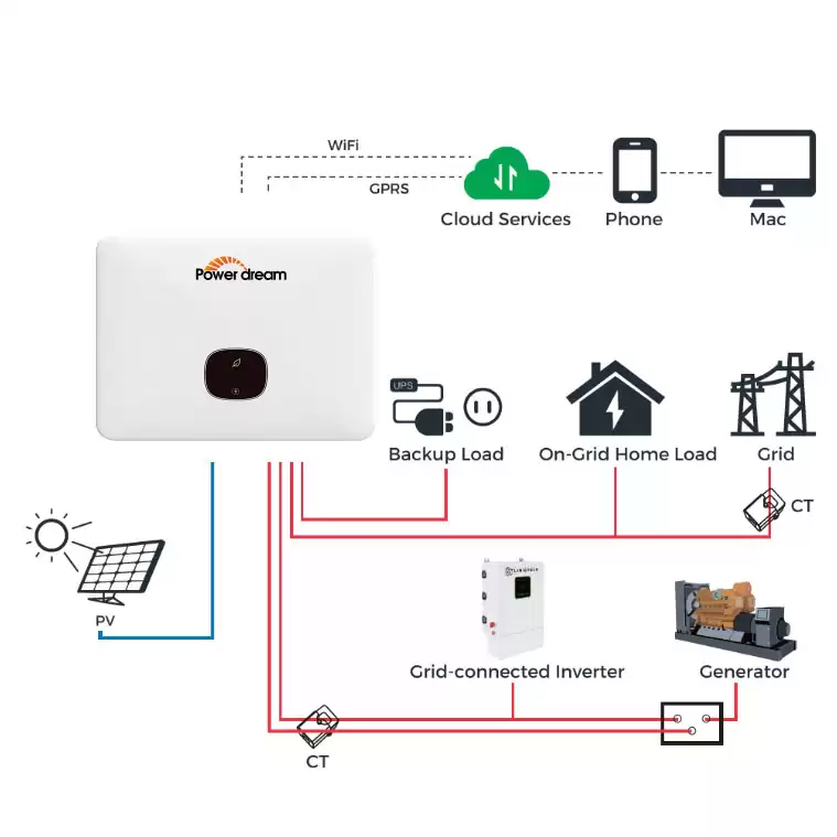
Protection Device, Grounding, Isolation, and System Architecture Requirements for On Grid Solar System
Compliant on grid solar systems incorporate protection devices and system architecture to isolate faults and prevent damage to equipment. Therefore, ensuring that appropriate protective components and cabling are included on the procurement list is a top priority. This includes basic protection and isolation elements, such as PV string fuses or DC circuit breakers, appropriately rated DC isolators, and rapid shutdown capabilities that comply with regulations (e.g., US NEC 690.12). Utility interconnection breakers, anti-islanding relays, and grid protection relays should be sized appropriately for the inverter and transformer ratings. Grounding protocols should also comply with local standards (TN/TT/IT) and address lightning protection issues through site-specific grounding designs.

Commissioning, Testing, and Long-Term Compliance Management
Achieving grid compliance ultimately requires documenting commissioning and establishing an ongoing compliance system. Procurement contracts should require grid-connected solar system suppliers to provide complete test evidence, commissioning reports, and a regular review plan.
Commissioning and acceptance testing requirements include factory acceptance test (FAT) documentation for key equipment (inverters, transformers, and relays), showing test procedures and pass/fail results. The site acceptance test program encompasses insulation resistance, polarity checks, protective relay functionality testing, islanding prevention verification, low-voltage ride-through (LVRT)/high-voltage ride-through (HVRT) testing, as well as short-circuit and protection coordination testing. PV strings undergo IV curve testing and performance verification (using calibrated IV tracers) to confirm expected energy production and identify underperforming strings.
Long-term compliance and maintenance of on grid solar systems requires regular reverification of relay settings, meter calibration, and SPD replacement. Additionally, you should maintain an audit trail, and a change control process must govern any parameter changes. Power Dream’s on grid solar systems come with comprehensive commissioning support and signed FAT/SAT documentation.
Adherence to system testing, setup verification, and contract compliance support.
A comprehensive grid compliance checklist for on grid solar systems helps you move from supplier declarations to verifiable interconnection readiness. Adhere to the requirements and standards mentioned above during procurement and operation. Power Dream’s on grid solar systems meet all the compliance elements mentioned above: our inverters are type-tested for islanding protection, low-voltage ride-through/fast ride-through, and voltage-var control. Furthermore, our protection and metering packages meet common utility requirements. Our commissioning team provides FAT/SAT documentation, relay settings, COMTRADE logs, and structured O&M services to ensure long-term compliance and operational efficiency.