How to effectively calculate the static load bearing structure of a ground mount solar system?
According to one of our survey reports, 8% of ground mount solar system failures are due to flawed static load-bearing structure calculations. For ground-mount users, this translates to an average repair cost of thousands of dollars per failure, in addition to 4-6 weeks of lost power generation while the system undergoes maintenance. Even worse, the same study revealed that 62% of these failures could have been avoided with proper load analysis. As a solar racking system provider, we combine site-specific data, advanced engineering techniques, and detailed design documentation (layout drawings, joint specifications, installation guides) to ensure your system can withstand a wide range of loads, addressing your biggest installation challenges and providing peace of mind.
What is the static load-bearing structure of a ground mount solar system?
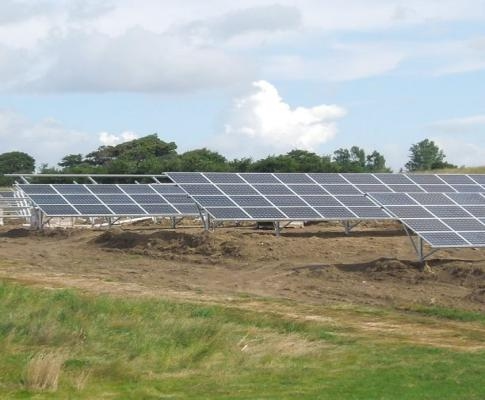
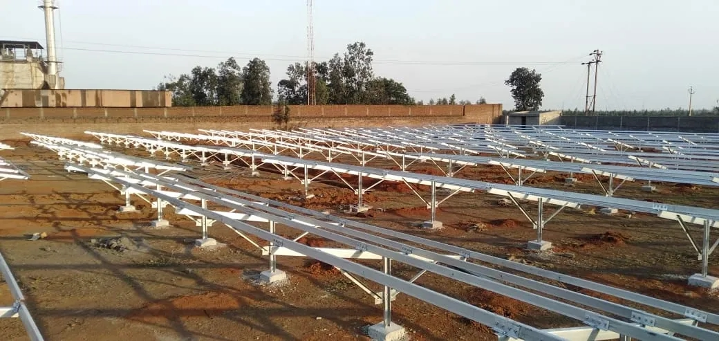
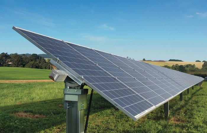
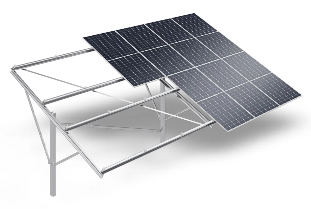
First, as a user, you need to understand the static load-bearing structure of a ground-mounted solar system and how it differs from other solar mounting systems. The static load-bearing structure refers to the framework that supports the solar array and prevents movement or deformation under constant (static) forces. For ground-mounted solar systems, this includes:
Foundation: The concrete foundation or anchor bolts that anchor the system to the soil.
Support columns: The metal or aluminum poles that connect the foundation to the track.
Tracks: The long beams that hold the solar panels.
Mounting hardware: The bolts, clamps, and brackets that secure the panels to the track.
Unlike dynamic loads, static loads act continuously. The system structure must withstand these forces. These loads can last for over 25 years without degradation. For example, a 5kW ground-mounted solar system has a static load of approximately 150 pounds per panel. This static load never dissipates, so the system structure must support it indefinitely. BARANA calculations ensure that every component, from half-inch bolts to 4-foot-tall columns, can withstand these long-term forces.
Calculating Critical Static Loads for Ground Mount Solar System
Effective static load calculations begin by determining all the forces acting on a ground-mounted solar system. BARANA analyzes three core load types and tailors the calculation to your site’s specific conditions:
1. Dead Loads
This is the fixed weight of the system itself, including the solar panels, rails, posts, and hardware, and the concrete foundation.
For a ground-mounted solar system with 20 solar panels, the total dead load is approximately 600-900 pounds. BARANA uses the exact specifications of your selected panels and solar racking system components to calculate this accurately to the nearest ounce.
2. Live Loads
Live loads are temporary forces, typically from maintenance workers. The International Building Code (IBC) requires a minimum of 250 pounds per worker for ground-mounted solar systems. Even if you do not plan on frequent maintenance, BARANA considers this in every calculation, as unexpected repairs require someone to stand on the rails.
3. Environmental Loads
These loads vary the most and are the most critical, as they depend on your location:
Wind Loads: Calculated based on National Oceanic and Atmospheric Administration (NOAA) data, for example, winds of 120 mph in Florida’s hurricane belt and 80 mph in tornado-prone areas of the Midwest. Miles per hour. Wind pushes against the solar panels, creating “lift” that pulls the system upward.
Snow load: Based on average local snowfall. Wet snow weighs more, so for areas with heavier wet snow, we use a compaction weight of 50 pounds per square foot.
Soil bearing capacity: Soil testing (required for all BARANA projects) tells us how much weight the ground can support, which determines the depth and type of foundation.
BARANA’s Four-Step Static Load Calculation Process
BARANA’s process is a site-specific, code-compliant workflow that eliminates risk. Here is how we calculate the static load-bearing structure of a ground mount solar system:
Step 1: Site Assessment
First, we gather field data to avoid making sweeping assumptions. Our engineers test your soil to measure its bearing capacity and drainage properties. We also obtain 30-year average wind and snow loads from the National Oceanic and Atmospheric Administration (NOAA) Climate Data Center. After determining the exact weight, size, and wind resistance data for your selected solar panels, we assess the load-bearing capacity of your soil.
Step 2: Load Quantification
We input all site data into our proprietary engineering software to calculate the magnitude of each load. For the dead load calculation, we factor in the combined weight of the panels, rails, and hardware. For live loads, we add 250 pounds for each potential worker position. We also calculate environmental loads such as wind pressure and snow weight.
Step 3: Structural Analysis
We use FEA software to simulate how each component will withstand the total load. We test whether the rails bend under the combined dead and snow loads and verify whether the columns tilt under wind loads. We also ensure that the foundation will not sink into the soil.
Step 4: Apply a Safety Factor
To account for unexpected forces, we multiply all loads by a safety factor according to IBC standards: dead load + live load x 1.5 times to ensure the structure can withstand a weight 50% higher than expected. Environmental load x 1.3 times. This process ensures your ground-mounted solar system not only meets code but also exceeds it.
BARANA Detailed Design Documents – Installation Guidelines
Calculations are meaningless without a clear execution plan. BARANA provides detailed design documents to ensure your ground mount solar system is installed correctly. These documents address the user’s primary concern: “Will the installer be able to install it correctly?” Our service includes three key components:
1. Layout Diagrams
2D/3D maps showing panel spacing, post location, and foundation location, along with instructions for setbacks (e.g., 5 feet from property line) and drainage (to prevent water accumulation around the foundation), as well as load labels for each section.
2. Mounting Joint Specifications
Includes precise bolt sizes, torque requirements, and joint cross-sections to prevent misalignment.
3. Installation Techniques
Foundation specifications: depth, concrete mix, and curing time, as well as track leveling tolerances and checkpoints.
Common Calculation Mistakes and BARANA’s Solutions
Even experienced installers can make mistakes in static load calculations, and BARANA’s process eliminates the most common pitfalls:
Mistake 1: Using Generic Weather Data
Problem: Installers rely on national averages instead of local data.
BARANA’s Solution: We use NOAA weather data. County-level data (e.g., 40 lbs/ft2 in northern Maine and 0 lbs/ft2 in southern California).
Mistake 2: Ignoring Soil Type
Problem: Skipping soil testing and using a standard foundation depth results in sinking in soft soils.
BARANA’s Solution: Soil testing is mandatory for every project, and we adjust foundation depth capacity based on soil bearing capacity.
Mistake 3: Forgetting Live Loads
Problem: Not accounting for maintenance workers, resulting in track bending when someone stands on it.
BARANA’s Solution: Including Live Loads in every calculation.
By addressing these mistakes upfront, we can better ensure your ground-mounted solar system avoids common failures with other systems.
Static Load Calculations: The Basics of Ground-Mounted Solar System Installation
For anyone considering installing a ground-mounted solar system, static load structural calculations are crucial in determining whether the system will last 25 years or fail within 5. BARANA We eliminate risks and address your biggest installation challenges based on field data, rigorous engineering, and detailed design documentation. We sell more than just solar mounting systems; we ensure your ground-mounted solar system is robust and durable, regardless of weather or time of year.

